 TAK Technology
Buck converter — output inductor
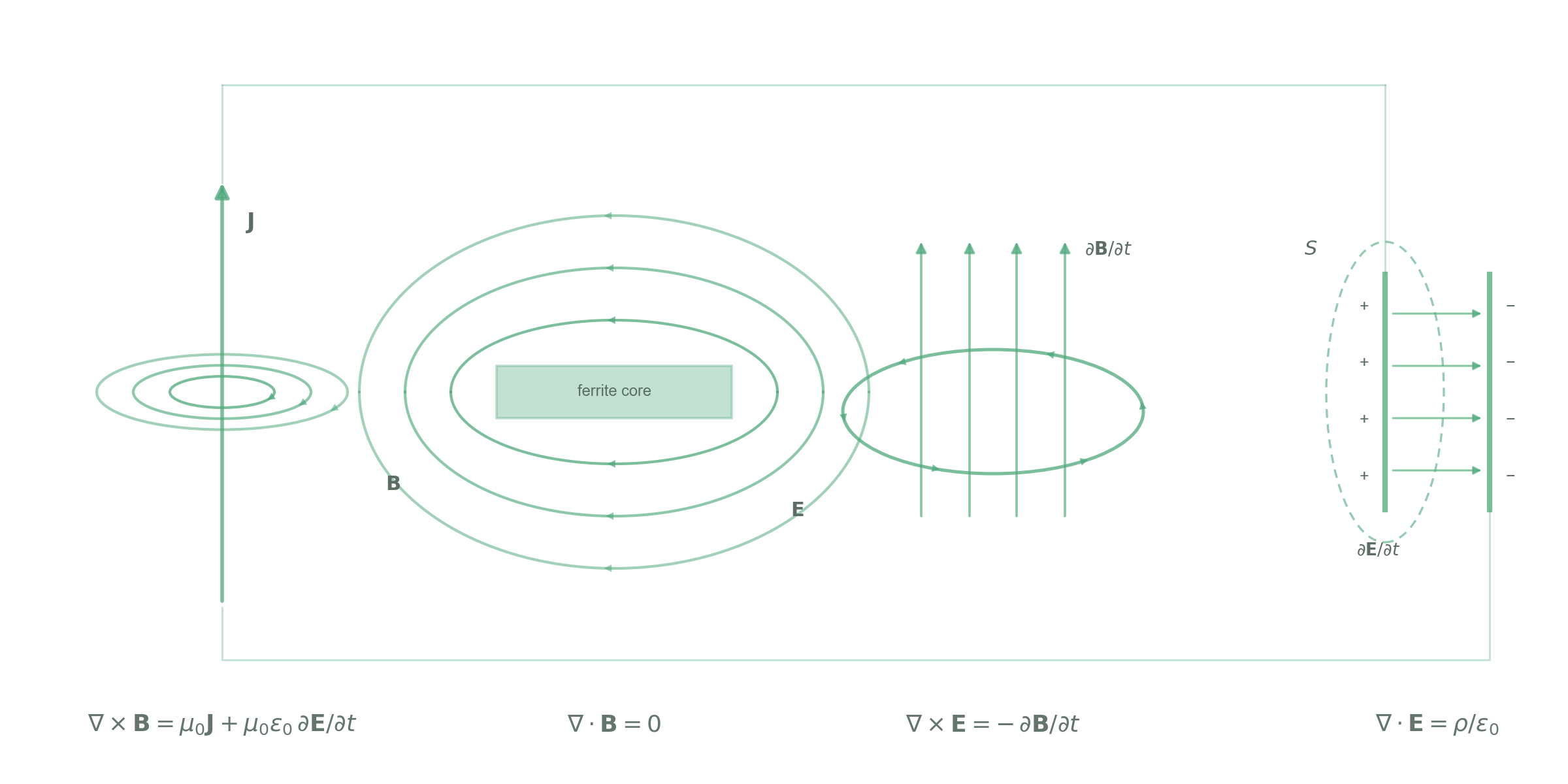
The inductor sits in series on the output side: large DC, small AC swing, so the design is governed by saturation (DC bias), not by core loss.
- LOutput storage inductorLook at hot Bs and the air gap first, then at loss; multiphase in parallel = VRM/TLVR
Band → material
| Band | First choice | Alternative | Note |
|---|---|---|---|
| Buck ≦0.1 MHz | TM82 | — | Bs 600 mT, gapped for DC bias |
| Buck 0.1–0.5 MHz | TM71 | — | By IDC: μi 3800 + high Bs |
| Buck 0.5–0.8 MHz | TM59★ | — | |
| Buck 0.8–3 MHz | TM65★ | TM61TM63 | |
| Buck ≦0.3 MHz | — | TM80TM83★TP44TP45 | When loss matters; high temperature (core up to 140 ℃) |
| VRM/TLVR ≦0.1 MHz | TM82 | — | |
| VRM/TLVR 0.1–0.5 MHz | TM71 | — | |
| VRM/TLVR 0.5–0.8 MHz | TM59★ | — | |
| VRM/TLVR 0.8–1 MHz | TM65★ | TM61 | |
| VRM/TLVR ≦0.3 MHz | — | TM80TM83★ | |
| NiZn | — | — | Parts on this page are mainly MnZn; no TAK NiZn counterpart is listed; for mA-level small inductors see circuit 11 |
Suggested shapes
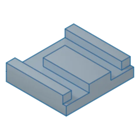 3D · illustrativeUDChoose a series ▾
Strengths
- Vertical mounting, small PCB footprint
- Suits high-current inductors with a single turn or copper-clip winding
- Withstands DC bias; switching frequencies of 0.7 MHz and above
Trade-offs
- Taller
- Mainly for high-current VRM/TLVR use
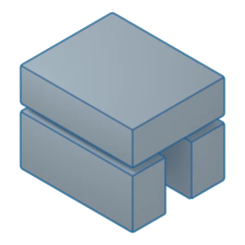 3D · illustrativeU+IChoose a series ▾
Strengths
- Horizontal U+I combination, low height
- Suits high-current inductors with a single turn or copper-clip winding
- Withstands DC bias; switching frequencies of 0.7 MHz and above
Trade-offs
- Larger PCB footprint
- Two-piece assembly; AL consistency must be controlled
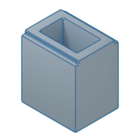 3D · illustrativeSP+IChoose a series ▾
Strengths
- Excellent shielding, low leakage flux
- Easy PCB mounting, easy winding
- Combines with I/R/DR into low-leakage SMD inductors
Trade-offs
- Weaker heat dissipation
- Two-piece assembly

Where it goes
VRM and TLVR for GPUs/CPUs; on-board PoL
ECU/ADAS processor power
On-board buck on motherboards, networking and industrial-control boards