 TAK Technology
Signal transformers — wideband, balun, current transformer
One transformer circuit: the primary takes the signal source or a through-core current, the secondary drives the load. The brackets after each band give the scenario (signal/CT); MnZn high-permeability in the low bands, NiZn above 1 MHz.
- TWideband signal transformer / balunMnZn high-permeability up to 1.5 MHz, TM63 for 1–5 MHz; above that NiZn along the μi ladder
- CTCurrent transformersThe primary is often a single turn through the core; high μi and low remanence keep the magnetizing current small and the measurement accurate
Band → material
| Band | First choice | Alternative | Note |
|---|---|---|---|
| ≤1.5 MHz (signal) | T05T10 | E02T12 | MnZn high-perm, chosen by μi |
| 1–5 MHz (signal) | TM63 | TM61TM65★ | Low-power wideband transformers with large signal swing / high bias |
| ≦1.5 MHz(CT) | T10T07 | T05T06E02T2 | |
| 1–5 MHz(CT) | — | TM63 | MHz CTs (CT) |
| ≤0.5 MHz (pulse/gate) | TM71 | T05 | High μi and high Bs for ungapped pulse / gate-drive cores |
| 1–5 MHz (pulse/gate) | — | TM63 | MHz gate drive |
| NiZn 1–2 MHz (signal) | DL3DL4 | — | Low-band baluns / wideband signal (catalogue frequency range) |
| NiZn 1–3.5 MHz (signal) | Q1C1 | — | Upper limit = lower of loss factor ≤2× its minimum and μ′ within 20 % of nominal |
| NiZn 1–6.7 MHz (signal) | M63 | — | |
| NiZn 1–7.7 MHz (signal) | M61 | — | |
| NiZn 1–15 MHz (signal) | — | M61H | |
| NiZn 1–25 MHz (signal) | M9A | — | |
| NiZn 1–30 MHz (signal) | V2F1 | — | |
| NiZn 1–50 MHz (signal) | — | M5E1 | Upper limit = lower of loss factor ≤2× its minimum and μ′ within 20 % of nominal |
| NiZn 1–55 MHz (signal) | — | V4F1 | |
| NiZn (CT) | — | — | No NiZn counterpart |
| NiZn (pulse/gate) | — | — | No NiZn counterpart |
Suggested shapes
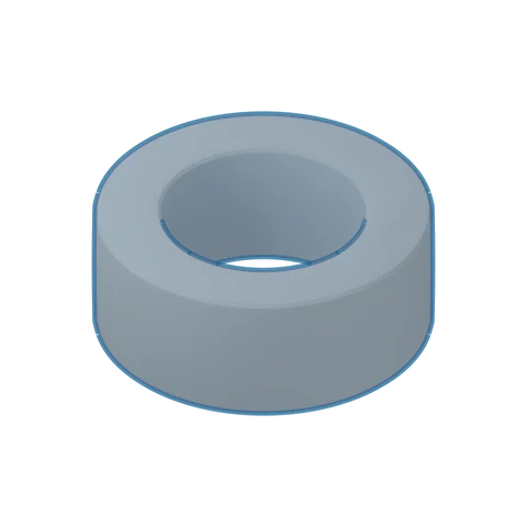 3D · illustrativeToroid TChoose a series ▾
Strengths
- Closed magnetic path without joints or air gap: highest magnetic efficiency
- Good self-shielding, low leakage flux
- Lowest core cost, no bobbin needed
Trade-offs
- Winding must be threaded through the hole; high winding cost
- Less convenient to mount on the PCB
- No air gap; for storage inductors use a combination shape whose gap can be ground
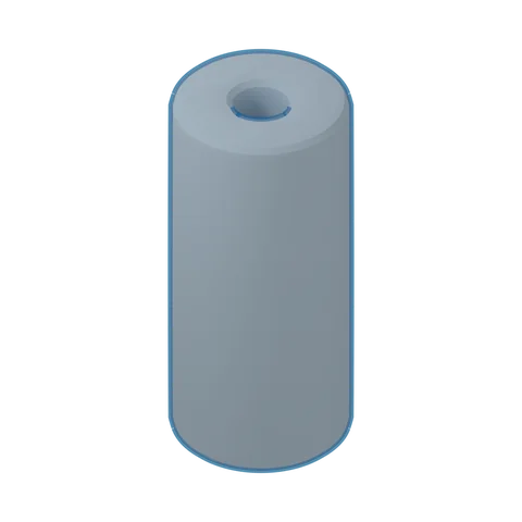 3D · illustrativeRHChoose a series ▾
Strengths
- Slips straight over a conductor or lead; no bobbin, simplest to fit
- For EMI suppression on cables/leads
Trade-offs
- Mainly threaded onto a conductor, not used as a wound inductor
- The suppression band depends on the material; choose the grade by band
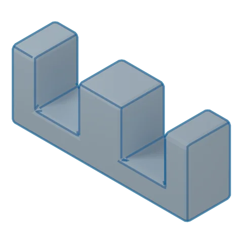 3D · illustrativeEEChoose a series ▾
Strengths
- Easiest bobbin winding and assembly
- Best heat dissipation
- Low core cost
Trade-offs
- Weak self-shielding, higher leakage flux
- Needs a bobbin; for low height use EFD
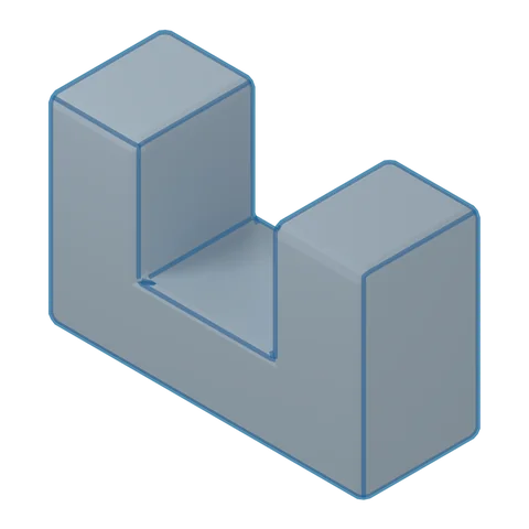 3D · illustrativeUUChoose a series ▾
Strengths
- Large window, easy to wind thick wire
- Suits high-voltage insulation and high power
Trade-offs
- Exposed winding, weak shielding
- Larger volume; mostly for PFC / high voltage / high power
Where it goes
Networking signal transformers · Ethernet isolation · PSU current sensing
In-vehicle communication isolation; current sensing in charging stations and OBCs
Meter CTs, inverter current feedback, wideband baluns