 TAK Technology
Chokes & filters — low-frequency chokes, SMD inductors, cost-effective grades
One series-inductor / LC-filter circuit, with the material chosen by scenario (shown in brackets after the band): MnZn high-Bs for ≤0.1 MHz low-frequency chokes; solder-heat-resistant NiZn for mA-level SMD inductors; Mg-based grades for cost-driven filters and beads.
- LLow-frequency choke / ballast inductor≤0.1 MHz; high Bs, including saturable reactors and magnetic amplifiers
- LSMD small inductor / filter inductormA level, solder-heat resistant, miniaturized; rated current is set by size and heat
Band → material
| Band | First choice | Alternative | Note |
|---|---|---|---|
| ≤0.1 MHz (low-frequency choke) | T2T2MTB2 | — | Magnetic amplifiers / saturable reactors / DC-biased chokes (Bs 580 / 460 mT) |
| NiZn (low-frequency choke) | — | — | No NiZn counterpart |
| NiZn ≤2 MHz (SMD small inductor) | DL3DL4 | — | mA-level SMD; loss-factor minimum 0.2 MHz |
| NiZn ≤2.5 MHz (SMD small inductor) | G5AG5B | — | mA-level SMD; loss-factor minimum 0.1 MHz |
| NiZn ≤3 MHz (SMD small inductor) | DL5H | — | |
| NiZn ≤3.5 MHz (SMD small inductor) | DL5 | — | |
| NiZn ≤3.6 MHz (SMD small inductor) | DL6 | — | |
| Mg-based ≤1.2 MHz (economy) | MF3 | — | RFID coils / wideband suppression rings |
| Mg-based ≤2 MHz (economy) | MG2 | — | Standard chokes / low-mid-frequency filters |
| Mg-based ≤3.5 MHz (economy) | MGB1 | — | Wideband EMI beads / mid-high-frequency filter inductors, Bs 380 / 320 mT |
| Mg-based 0.1–0.7 MHz (economy) | MF2 | — | Large mains-input CM chokes / cable rings; Tc >130 ℃, Bs 95 mT at 100 ℃ — room-temperature use only |
| Mg-based 0.1–1.4 MHz (economy) | MF1 | — | RF / IF filters, resonant inductors (μ180) |
Suggested shapes
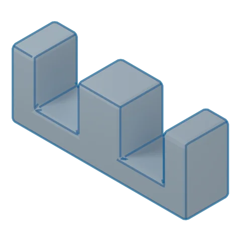 3D · illustrativeEE (low-frequency choke)Choose a series ▾
Strengths
- Easiest bobbin winding and assembly
- Best heat dissipation
- Low core cost
Trade-offs
- Weak self-shielding, higher leakage flux
- Needs a bobbin; for low height use EFD
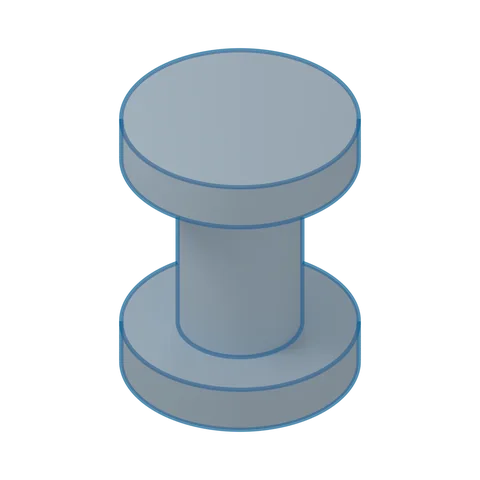 3D · illustrativeDR drum coreChoose a series ▾
Strengths
- Open magnetic circuit, withstands DC bias
- Simplest winding
- Can be paired with an SP/SRI shield cap to reduce leakage flux
Trade-offs
- High leakage flux when used alone; watch EMI
- Inductance limited by the open magnetic circuit
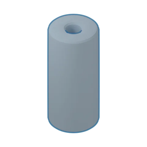 3D · illustrativeRH beadChoose a series ▾
Strengths
- Slips straight over a conductor or lead; no bobbin, simplest to fit
- For EMI suppression on cables/leads
Trade-offs
- Mainly threaded onto a conductor, not used as a wound inductor
- The suppression band depends on the material; choose the grade by band
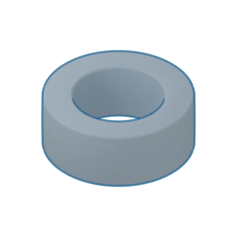 3D · illustrativeToroid TChoose a series ▾
Strengths
- Closed magnetic path without joints or air gap: highest magnetic efficiency
- Good self-shielding, low leakage flux
- Lowest core cost, no bobbin needed
Trade-offs
- Winding must be threaded through the hole; high winding cost
- Less convenient to mount on the PCB
- No air gap; for storage inductors use a combination shape whose gap can be ground
Where it goes
UPS low-frequency chokes; motherboard power-rail filtering
Sensor and ECU power filtering
Lighting ballasts; phone/wearable power rails, USB-cable EMI