Applications: AI data center, from rack to GPU
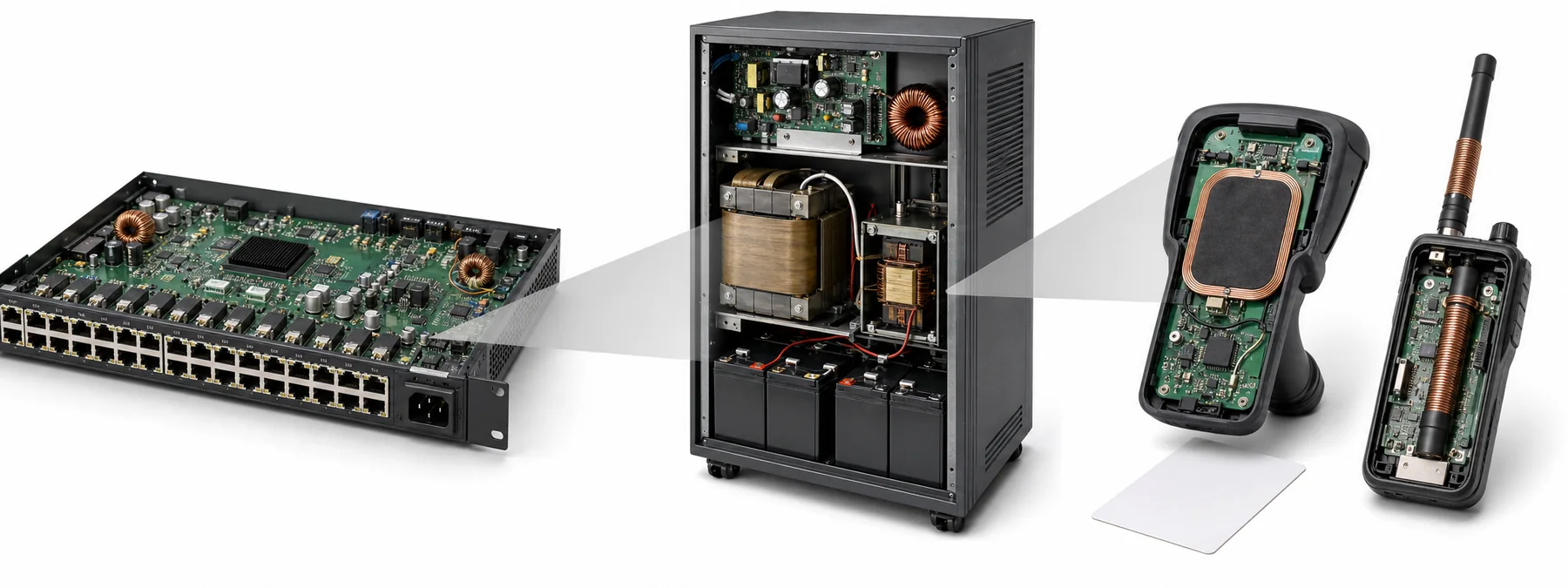
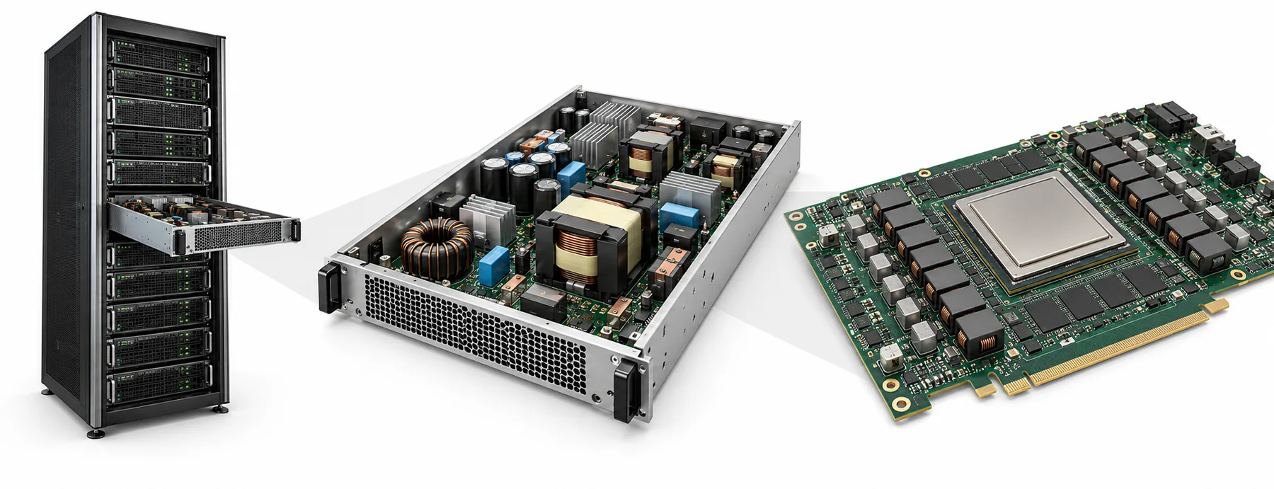
Following the power path from the rack to the GPU: the common-mode choke where AC enters the rack, the LLC isolation transformer and resonant inductor in the power supply, and the TLVR multiphase coupled inductor on the GPU board.
AI servers keep raising frequency and current — exactly where the two new grades TM59★ and TM65★ are positioned.
01 02 03 04 01 Input common-mode choke Suppresses common-mode noise on the power line. Toroid T Core | T10 · T12.
T10 VERY-HIGH PERMEABILITY LOW-REMANENCE FERRITE T12 ULTRA-HIGH PERMEABILITY FERRITE 02 LLC isolation transformer High-frequency isolated step-down, 300–550 kHz. PQ · planar | TM59★.
TM59★ MID-HIGH-FREQUENCY LOW-LOSS POWER FERRITE 03 LLC resonant inductor Works in the same band as the main transformer. PQ · EQ | TM59★.
TM59★ MID-HIGH-FREQUENCY LOW-LOSS POWER FERRITE 04 GPU power TLVR Multiphase coupled inductor, material chosen by IDC (UI for VRM). UD | TM59★ · TM65★.
TM59★ MID-HIGH-FREQUENCY LOW-LOSS POWER FERRITE TM65★ HIGH-FREQUENCY INDUCTOR POWER FERRITE New architectures 800 V direct conversion Approx. 1 MHz | TM63 candidate.
TM63 HIGH-FREQUENCY LOW-LOSS POWER FERRITE 48/54 V→12 V IBC TM59★。
TM59★ MID-HIGH-FREQUENCY LOW-LOSS POWER FERRITE On-board beads · rings ME03★・L43。
ME03★ EMI Suppression Ferrite L43 HIGH PERM. & EMI MATERIALS Common-mode choke — EMI filtering
Two windings in the same sense on one core: common-mode flux adds up to a high impedance, while the flux of the differential-mode operating current cancels. Choose the material by impedance vs. frequency.
L1/L2 Common-mode chokeChoose by the impedance peak in the band to be suppressed, not by inductance CIRCUIT · CMC L1 / L L2 / N N turns Icm → Icm → Band → material Band First choice Alternative Note ≦2 MHz T10 T12 T05 Tc >110 ℃, Bs 210 mT at 100 ℃ — leave margin when hot ≦30 MHz — E02 2–30 MHz overlap band NiZn 2–30 MHz L22A L28A SL50 SL80 G5A G5B NiZn 2–300 MHz L43 L8A L6A — Overlaps MnZn at 2–30 MHz; measured RH5 Z still rising at 300 MHz
2–30 MHz is the MnZn/NiZn overlap band: meet the low-frequency Z first, then keep the high-frequency Z as high as possible. For beads and sleeves see the last page, "EMI band overview".
Suggested shapes 3D · illustrative Toroid T Choose a series ▾ Strengths Closed magnetic path without joints or air gap: highest magnetic efficiency Good self-shielding, low leakage flux Lowest core cost, no bobbin needed Trade-offs Winding must be threaded through the hole; high winding cost Less convenient to mount on the PCB No air gap; for storage inductors use a combination shape whose gap can be ground 3D · illustrative UU/UT Choose a series ▾ Strengths Large window, easy to wind thick wire Suits high-voltage insulation and high power Trade-offs Exposed winding, weak shielding Larger volume; mostly for PFC / high voltage / high power 3D · illustrative RH bead Choose a series ▾ Strengths Slips straight over a conductor or lead; no bobbin, simplest to fit For EMI suppression on cables/leads Trade-offs Mainly threaded onto a conductor, not used as a wound inductor The suppression band depends on the material; choose the grade by band 3D · illustrative DR + plate Choose a series ▾ Strengths Open magnetic circuit, withstands DC bias Simplest winding Can be paired with an SP/SRI shield cap to reduce leakage flux Trade-offs High leakage flux when used alone; watch EMI Inductance limited by the open magnetic circuit Where it goes AI data center
AC input filter of every power supply
New-energy vehicles
In-vehicle CAN/Ethernet, high-voltage harness EMI
Consumer · industrial
Power inputs, USB/data cables
Half-bridge LLC — transformer & resonant inductor
Lr–Cr–Lm resonance gives zero-voltage switching; the transformer sets Lm with its air gap, and Lr is often integrated as leakage inductance. Choose the material by operating frequency first.
Np/Ns LLC main transformer (gapped for Lm)The worst case is at the lowest operating frequency Lr Resonant inductorSame band as the main transformer; choose the material for that band CIRCUIT · LLC Vin S1 S2 Lr Cr Np Ns ×2 D1 D2 C R Vo Band → material Band First choice Alternative Note ≦0.3 MHz TM83★ TM80 TM81 TP40 TP44 TP45 0.3–1 MHz TM59★ TM50A TM65★ Only above 300 kHz 1–5 MHz TM63 TM61 First choice for small-size MHz transformers (lowest loss) NiZn — — No TAK NiZn grade listed: mainstream designs use MnZn; TAK has no 4F1-class NiZn power grade
Transformers ≤0.3 MHz: TM8x first, chosen by optimal operating temperature range (TP as alternates); >0.3 MHz: TM5x first.
Optimal operating temperature (℃): TM83★ 25–140, TM80 25–100, TM81 25–120, TM59★ 25–100, TM63 40–80.
Suggested shapes 3D · illustrative PQ Choose a series ▾ Strengths Optimized for switch-mode power: good ratio of volume, winding window and magnetic cross-section Center leg can be ground for an air gap to set AL Simple winding and assembly, good heat dissipation Trade-offs Higher core and bobbin cost Moderate shielding; less convenient to mount on the PCB 3D · illustrative ER / ER+I (planar) Choose a series ▾ Strengths Round center leg suits thick wire; lower winding loss Good heat dissipation, easy winding Trade-offs Weak self-shielding Moderate bobbin cost; less convenient to mount on the PCB 3D · illustrative EE/ETD Choose a series ▾ Strengths Easiest bobbin winding and assembly Best heat dissipation Low core cost Trade-offs Weak self-shielding, higher leakage flux Needs a bobbin; for low height use EFD 3D · illustrative RM(Lr) Choose a series ▾ Strengths Saves PCB area; low height possible Encloses the winding: good shielding, good heat dissipation Center leg can be ground for an air gap to set AL Trade-offs Higher core cost Lead-out of thick wire is limited Where it goes AI data center
Server PSU DC/DC stage; rack 800 V→50 V
New-energy vehicles
OBC (CLLC), high voltage to 12 V
Consumer · industrial
Charging-station modules, telecom power, TV power
Buck converter — output inductor
The inductor sits in series on the output side: large DC, small AC swing, so the design is governed by saturation (DC bias), not by core loss.
L Output storage inductorLook at hot Bs and the air gap first, then at loss; multiphase in parallel = VRM/TLVR CIRCUIT · BUCK Vin S L D C R Vo Band → material Band First choice Alternative Note Buck ≦0.1 MHz TM82 — Bs 600 mT, gapped for DC bias Buck 0.1–0.5 MHz TM71 — By IDC: μi 3800 + high Bs Buck 0.5–0.8 MHz TM59★ — Buck 0.8–3 MHz TM65★ TM61 TM63 Buck ≦0.3 MHz — TM80 TM83★ TP44 TP45 When loss matters; high temperature (core up to 140 ℃) VRM/TLVR ≦0.1 MHz TM82 — VRM/TLVR 0.1–0.5 MHz TM71 — VRM/TLVR 0.5–0.8 MHz TM59★ — VRM/TLVR 0.8–1 MHz TM65★ TM61 VRM/TLVR ≦0.3 MHz — TM80 TM83★ NiZn — — Parts on this page are mainly MnZn; no TAK NiZn counterpart is listed; for mA-level small inductors see circuit 11
Suggested shapes 3D · illustrative UD Choose a series ▾ Strengths Vertical mounting, small PCB footprint Suits high-current inductors with a single turn or copper-clip winding Withstands DC bias; switching frequencies of 0.7 MHz and above Trade-offs Taller Mainly for high-current VRM/TLVR use 3D · illustrative U+I Choose a series ▾ Strengths Horizontal U+I combination, low height Suits high-current inductors with a single turn or copper-clip winding Withstands DC bias; switching frequencies of 0.7 MHz and above Trade-offs Larger PCB footprint Two-piece assembly; AL consistency must be controlled 3D · illustrative SP+I Choose a series ▾ Strengths Excellent shielding, low leakage flux Easy PCB mounting, easy winding Combines with I/R/DR into low-leakage SMD inductors Trade-offs Weaker heat dissipation Two-piece assembly 3D · illustrative DR (NiZn, mA level) Choose a series ▾ Strengths Open magnetic circuit, withstands DC bias Simplest winding Can be paired with an SP/SRI shield cap to reduce leakage flux Trade-offs High leakage flux when used alone; watch EMI Inductance limited by the open magnetic circuit Where it goes AI data center
VRM and TLVR for GPUs/CPUs; on-board PoL
New-energy vehicles
ECU/ADAS processor power
Consumer · industrial
On-board buck on motherboards, networking and industrial-control boards
★ = 2027 new material.Equipment shown is a generic illustration and does not imply supply to the end products pictured; materials are selection candidates and must be verified under actual conditions.
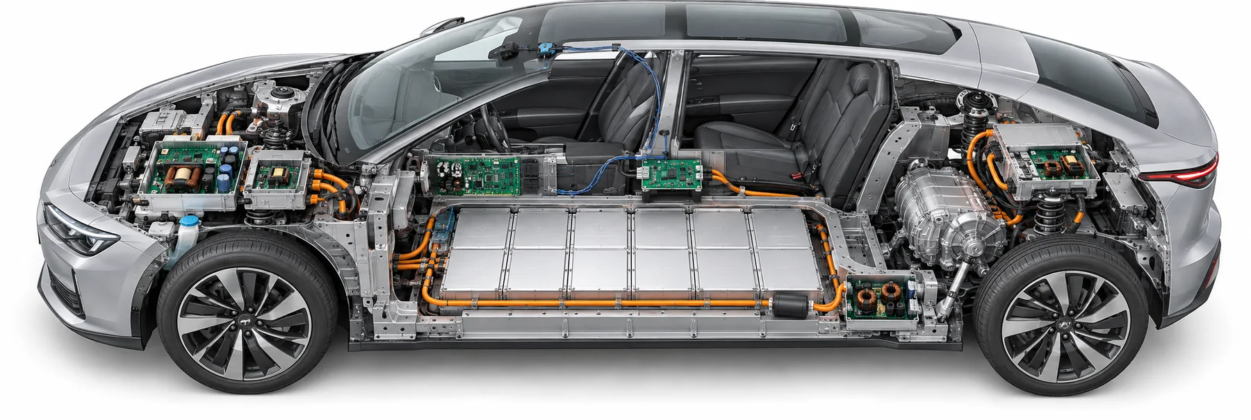
Applications: new-energy vehicles — power, communication and EMI
From charging and high-voltage conversion to the in-vehicle network, cores are spread along the vehicle's power and signal paths. Automotive demands wide temperature — TM83★ keeps its low loss at a core temperature of 140 ℃.
01 02 03 04 05 06 01 On-board charger (OBC) CLLC main transformer · PQ/planar | TM83★ · TM59★.
TM83★ FULL-TEMPERATURE-RANGE LOW-LOSS POWER FERRITE TM59★ MID-HIGH-FREQUENCY LOW-LOSS POWER FERRITE 02 High voltage to 12 V DC/DC Approx. 100 kHz · PQ/EE | TM80 · TM83★.
TM80 WIDE-TEMPERATURE LOW-LOSS POWER FERRITE TM83★ FULL-TEMPERATURE-RANGE LOW-LOSS POWER FERRITE 03 Traction inverter Isolated bias supply · EP/EE | TM71.
TM71 HIGH-PERMEABILITY POWER FERRITE 04 48 V mild hybrid (alternative architecture) Storage inductor · 100–200 kHz · ER | TM71.
TM71 HIGH-PERMEABILITY POWER FERRITE 05 In-vehicle communication filtering Communication common mode: DR + plate | L43 · SL50/80; camera PoC inductors: G5A/G5B (candidate materials).
L43 HIGH PERM. & EMI MATERIALS SL50 WIDE TEMP STABLE MATERIALS SL80 WIDE TEMP STABLE MATERIALS G5A HIGH PERM. & HIGH FLUX & EMI MATERIALS G5B HIGH PERM. & HIGH FLUX & EMI MATERIALS 06 High-voltage busbar · harness EMI Rings for busbars and high-voltage cables · toroid/clamp | T10 · ME03★ · L43.
T10 VERY-HIGH PERMEABILITY LOW-REMANENCE FERRITE ME03★ EMI Suppression Ferrite L43 HIGH PERM. & EMI MATERIALS Half-bridge LLC — transformer & resonant inductor
Lr–Cr–Lm resonance gives zero-voltage switching; the transformer sets Lm with its air gap, and Lr is often integrated as leakage inductance. Choose the material by operating frequency first.
Np/Ns LLC main transformer (gapped for Lm)The worst case is at the lowest operating frequency Lr Resonant inductorSame band as the main transformer; choose the material for that band CIRCUIT · LLC Vin S1 S2 Lr Cr Np Ns ×2 D1 D2 C R Vo Band → material Band First choice Alternative Note ≦0.3 MHz TM83★ TM80 TM81 TP40 TP44 TP45 0.3–1 MHz TM59★ TM50A TM65★ Only above 300 kHz 1–5 MHz TM63 TM61 First choice for small-size MHz transformers (lowest loss) NiZn — — No TAK NiZn grade listed: mainstream designs use MnZn; TAK has no 4F1-class NiZn power grade
Transformers ≤0.3 MHz: TM8x first, chosen by optimal operating temperature range (TP as alternates); >0.3 MHz: TM5x first.
Optimal operating temperature (℃): TM83★ 25–140, TM80 25–100, TM81 25–120, TM59★ 25–100, TM63 40–80.
Suggested shapes 3D · illustrative PQ Choose a series ▾ Strengths Optimized for switch-mode power: good ratio of volume, winding window and magnetic cross-section Center leg can be ground for an air gap to set AL Simple winding and assembly, good heat dissipation Trade-offs Higher core and bobbin cost Moderate shielding; less convenient to mount on the PCB 3D · illustrative ER / ER+I (planar) Choose a series ▾ Strengths Round center leg suits thick wire; lower winding loss Good heat dissipation, easy winding Trade-offs Weak self-shielding Moderate bobbin cost; less convenient to mount on the PCB 3D · illustrative EE/ETD Choose a series ▾ Strengths Easiest bobbin winding and assembly Best heat dissipation Low core cost Trade-offs Weak self-shielding, higher leakage flux Needs a bobbin; for low height use EFD 3D · illustrative RM(Lr) Choose a series ▾ Strengths Saves PCB area; low height possible Encloses the winding: good shielding, good heat dissipation Center leg can be ground for an air gap to set AL Trade-offs Higher core cost Lead-out of thick wire is limited Where it goes AI data center
Server PSU DC/DC stage; rack 800 V→50 V
New-energy vehicles
OBC (CLLC), high voltage to 12 V
Consumer · industrial
Charging-station modules, telecom power, TV power
Push-pull converter — centre-tapped transformer
Two switches conduct alternately and excite the core symmetrically in both directions; more power per core size than unipolar topologies, but margin must be left for flux walking.
Np×2/Ns×2 Push-pull transformerBipolar excitation; ideally no DC, in practice leave margin for flux walking L Output inductorRipple frequency 2·fsw; same material choice as the buck output inductor CIRCUIT · PUSHPULL Vin Np ×2 S1 S2 Ns ×2 D1 D2 L C R Vo Band → material Band First choice Alternative Note Transformer ≤0.3 MHz TM80 TM81 TM83★ TP44 TP45 TP40 Transformer 0.3–0.5 MHz TM59★ TM50A TM5x first above 0.3 MHz Output inductor ≤0.1 MHz TM82 — Bs 600 mT, gapped for DC bias Output inductor 0.1–0.5 MHz TM71 — By IDC: μi 3800 + high Bs Output inductor 0.5–0.8 MHz TM59★ — Output inductor 0.8–3 MHz TM65★ TM61 Output inductor ≤0.3 MHz — TM80 TM83★ When loss matters; high temperature (core up to 140 ℃) NiZn — — Parts on this page are mainly MnZn; no TAK NiZn counterpart is listed; for mA-level small inductors see circuit 11
Transformers ≤0.3 MHz: TM8x first, chosen by optimal operating temperature range (TP as alternates); >0.3 MHz: TM5x first.
Optimal operating temperature (℃), push-pull transformer: TM80 25–100, TM81 25–120, TM83★ 25–140, TM59★ 25–100.
Suggested shapes 3D · illustrative EE/EP Choose a series ▾ Strengths Easiest bobbin winding and assembly Best heat dissipation Low core cost Trade-offs Weak self-shielding, higher leakage flux Needs a bobbin; for low height use EFD 3D · illustrative RM Choose a series ▾ Strengths Saves PCB area; low height possible Encloses the winding: good shielding, good heat dissipation Center leg can be ground for an air gap to set AL Trade-offs Higher core cost Lead-out of thick wire is limited 3D · illustrative Toroid T Choose a series ▾ Strengths Closed magnetic path without joints or air gap: highest magnetic efficiency Good self-shielding, low leakage flux Lowest core cost, no bobbin needed Trade-offs Winding must be threaded through the hole; high winding cost Less convenient to mount on the PCB No air gap; for storage inductors use a combination shape whose gap can be ground 3D · illustrative PQ Choose a series ▾ Strengths Optimized for switch-mode power: good ratio of volume, winding window and magnetic cross-section Center leg can be ground for an air gap to set AL Simple winding and assembly, good heat dissipation Trade-offs Higher core and bobbin cost Moderate shielding; less convenient to mount on the PCB Where it goes AI data center
UPS, battery-backup conversion
New-energy vehicles
Isolated gate-drive supplies for traction inverters
Consumer · industrial
12/24 V low-voltage input converters, inverters
Boost converter — input inductor
The inductor sits on the input side and its average current equals the input current (larger than the output current); the worst case is at the lowest input voltage.
L Boost storage inductorCheck saturation at minimum input voltage and maximum load; adjust AL with the air gap CIRCUIT · BOOST Vin L S D C R Vo Band → material Band First choice Alternative Note ≦0.1 MHz TM82 — Bs 600 mT, gapped for DC bias 0.1–0.5 MHz TM71 — By IDC: μi 3800 + high Bs 0.5–0.8 MHz TM59★ — 0.8–3 MHz TM65★ TM61 ≦0.3 MHz — TM80 TM83★ When loss matters; high temperature (core up to 140 ℃) NiZn — — No TAK NiZn grade listed: high-current / high-flux designs use MnZn; for mA-level parts see SMD HF low-power inductors
Suggested shapes 3D · illustrative PQ Choose a series ▾ Strengths Optimized for switch-mode power: good ratio of volume, winding window and magnetic cross-section Center leg can be ground for an air gap to set AL Simple winding and assembly, good heat dissipation Trade-offs Higher core and bobbin cost Moderate shielding; less convenient to mount on the PCB 3D · illustrative RM Choose a series ▾ Strengths Saves PCB area; low height possible Encloses the winding: good shielding, good heat dissipation Center leg can be ground for an air gap to set AL Trade-offs Higher core cost Lead-out of thick wire is limited 3D · illustrative ER Choose a series ▾ Strengths Round center leg suits thick wire; lower winding loss Good heat dissipation, easy winding Trade-offs Weak self-shielding Moderate bobbin cost; less convenient to mount on the PCB 3D · illustrative Toroid T Choose a series ▾ Strengths Closed magnetic path without joints or air gap: highest magnetic efficiency Good self-shielding, low leakage flux Lowest core cost, no bobbin needed Trade-offs Winding must be threaded through the hole; high winding cost Less convenient to mount on the PCB No air gap; for storage inductors use a combination shape whose gap can be ground Where it goes AI data center
Backup-battery boost
New-energy vehicles
Storage inductors for 48 V mild-hybrid bidirectional DC/DC
Consumer · industrial
Solar MPPT, LED drivers, battery boost
Common-mode choke — EMI filtering
Two windings in the same sense on one core: common-mode flux adds up to a high impedance, while the flux of the differential-mode operating current cancels. Choose the material by impedance vs. frequency.
L1/L2 Common-mode chokeChoose by the impedance peak in the band to be suppressed, not by inductance CIRCUIT · CMC L1 / L L2 / N N turns Icm → Icm → Band → material Band First choice Alternative Note ≦2 MHz T10 T12 T05 Tc >110 ℃, Bs 210 mT at 100 ℃ — leave margin when hot ≦30 MHz — E02 2–30 MHz overlap band NiZn 2–30 MHz L22A L28A SL50 SL80 G5A G5B NiZn 2–300 MHz L43 L8A L6A — Overlaps MnZn at 2–30 MHz; measured RH5 Z still rising at 300 MHz
2–30 MHz is the MnZn/NiZn overlap band: meet the low-frequency Z first, then keep the high-frequency Z as high as possible. For beads and sleeves see the last page, "EMI band overview".
Suggested shapes 3D · illustrative Toroid T Choose a series ▾ Strengths Closed magnetic path without joints or air gap: highest magnetic efficiency Good self-shielding, low leakage flux Lowest core cost, no bobbin needed Trade-offs Winding must be threaded through the hole; high winding cost Less convenient to mount on the PCB No air gap; for storage inductors use a combination shape whose gap can be ground 3D · illustrative UU/UT Choose a series ▾ Strengths Large window, easy to wind thick wire Suits high-voltage insulation and high power Trade-offs Exposed winding, weak shielding Larger volume; mostly for PFC / high voltage / high power 3D · illustrative RH bead Choose a series ▾ Strengths Slips straight over a conductor or lead; no bobbin, simplest to fit For EMI suppression on cables/leads Trade-offs Mainly threaded onto a conductor, not used as a wound inductor The suppression band depends on the material; choose the grade by band 3D · illustrative DR + plate Choose a series ▾ Strengths Open magnetic circuit, withstands DC bias Simplest winding Can be paired with an SP/SRI shield cap to reduce leakage flux Trade-offs High leakage flux when used alone; watch EMI Inductance limited by the open magnetic circuit Where it goes AI data center
AC input filter of every power supply
New-energy vehicles
In-vehicle CAN/Ethernet, high-voltage harness EMI
Consumer · industrial
Power inputs, USB/data cables
★ = 2027 new material.Positions are illustrative across different vehicle architectures, not a bill of materials for a single model; materials must be verified for frequency, flux, temperature, bias current and impedance.
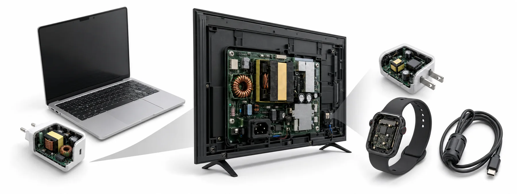
Applications: consumer electronics, from socket to fingertip
Laptop and phone chargers, the power board in a TV, the wearable on your wrist, a USB cable on the desk — in everyday life the cores stay out of sight, each doing its job.
Adapters Motherboard TV Power Phone Wearables USB Adapters flyback transformer Phone/laptop chargers, adapters | 04 Flyback: flyback transformer (gapped).
PFC choke Adapters above 75 W | 03 Boost PFC: PFC choke.
Motherboard buck On-board buck on motherboards | 01 Buck: output storage inductor.
TV power · LLC TV power | 07 Half-bridge LLC: LLC main transformer, resonant inductor.
Power input · common-mode choke Power input | 08 Common-mode choke: common-mode choke.
Phone chargers · flyback transformer Phone chargers | 04 Flyback: flyback transformer (gapped).
Wearables · power-rail filtering Phone/wearable power rails | 11 Chokes & filters: SMD small inductor / filter inductor.
USB cables · EMI USB/data cables, USB-cable EMI | 08 Common-mode choke · 11 Chokes & filters.
Flyback converter — energy-storage transformer
The transformer is also the storage inductor: it stores energy during the on-time and releases it through the secondary during the off-time; the design centres on stored energy and the air gap.
Np/Ns Flyback transformer (gapped)≤150 W mainly stores energy: choose by IDC (as inductors); >150 W: choose by loss CIRCUIT · FLYBACK Vin Np S Ns D C R Vo Band → material Band First choice Alternative Note ≦150 W ≦0.1 MHz TM82 — Bs 600 mT, gapped for DC bias ≦150 W 0.1–0.5 MHz TM71 — By IDC: μi 3800 + high Bs ≦150 W 0.5–0.8 MHz TM59★ — ≦150 W 0.8–3 MHz TM65★ — ≦150 W ≦0.3 MHz — TM80 TM83★ When loss matters; high temperature (core up to 140 ℃) >150 W ≦0.3 MHz TM80 TM81 TM83★ TP44 TP45 TP40 >150 W 0.3–1 MHz TM59★ TM50A TM65★ TM5x first above 0.3 MHz >150 W 1–3 MHz — TM61 NiZn — — Parts on this page are mainly MnZn; no TAK NiZn counterpart is listed
Transformers ≤0.3 MHz: TM8x first, chosen by optimal operating temperature range (TP as alternates); >0.3 MHz: TM5x first.
Optimal operating temperature (℃), flyback >150 W: TM80 25–100, TM81 25–120, TM83★ 25–140, TM59★ 25–100.
Suggested shapes 3D · illustrative EE/EFD Choose a series ▾ Strengths Easiest bobbin winding and assembly Best heat dissipation Low core cost Trade-offs Weak self-shielding, higher leakage flux Needs a bobbin; for low height use EFD 3D · illustrative RM Choose a series ▾ Strengths Saves PCB area; low height possible Encloses the winding: good shielding, good heat dissipation Center leg can be ground for an air gap to set AL Trade-offs Higher core cost Lead-out of thick wire is limited 3D · illustrative PQ Choose a series ▾ Strengths Optimized for switch-mode power: good ratio of volume, winding window and magnetic cross-section Center leg can be ground for an air gap to set AL Simple winding and assembly, good heat dissipation Trade-offs Higher core and bobbin cost Moderate shielding; less convenient to mount on the PCB 3D · illustrative ER Choose a series ▾ Strengths Round center leg suits thick wire; lower winding loss Good heat dissipation, easy winding Trade-offs Weak self-shielding Moderate bobbin cost; less convenient to mount on the PCB Where it goes AI data center
Standby / auxiliary supplies
New-energy vehicles
BMS and in-vehicle auxiliary power
Consumer · industrial
Phone/laptop chargers, adapters
Boost PFC — PFC choke
Rectified half-sine input with the duty cycle varying continuously over each mains cycle; check saturation at the peak current of the lowest mains voltage — choose by IDC, not by loss.
L PFC chokeHigh L, many turns; same material choice as the boost input inductor CIRCUIT · PFC ~ BR + L S D C R Vo Band → material Band First choice Alternative Note ≦0.1 MHz TM82 — Bs 600 mT, gapped for DC bias 0.1–0.5 MHz TM71 — By IDC: μi 3800 + high Bs 0.5–0.8 MHz TM59★ — 0.8–3 MHz TM65★ TM61 ≦0.3 MHz — TM80 TM83★ When loss matters; high temperature (core up to 140 ℃) NiZn — — No TAK NiZn grade listed: high-current / high-flux designs use MnZn; for mA-level parts see SMD HF low-power inductors
Powder-core toroids are also common for CCM PFC; ferrite has the advantage at higher frequencies or in CRM designs.
Suggested shapes 3D · illustrative PQ Choose a series ▾ Strengths Optimized for switch-mode power: good ratio of volume, winding window and magnetic cross-section Center leg can be ground for an air gap to set AL Simple winding and assembly, good heat dissipation Trade-offs Higher core and bobbin cost Moderate shielding; less convenient to mount on the PCB 3D · illustrative ER Choose a series ▾ Strengths Round center leg suits thick wire; lower winding loss Good heat dissipation, easy winding Trade-offs Weak self-shielding Moderate bobbin cost; less convenient to mount on the PCB 3D · illustrative U(PFC) Choose a series ▾ Strengths Large window, easy to wind thick wire Suits high-voltage insulation and high power Trade-offs Exposed winding, weak shielding Larger volume; mostly for PFC / high voltage / high power 3D · illustrative EE Choose a series ▾ Strengths Easiest bobbin winding and assembly Best heat dissipation Low core cost Trade-offs Weak self-shielding, higher leakage flux Needs a bobbin; for low height use EFD Where it goes AI data center
Front-end PFC in server and rack power supplies
New-energy vehicles
Front end of DC charging-station modules
Consumer · industrial
Adapters above 75 W, industrial power supplies, inverter appliances
Buck converter — output inductor
The inductor sits in series on the output side: large DC, small AC swing, so the design is governed by saturation (DC bias), not by core loss.
L Output storage inductorLook at hot Bs and the air gap first, then at loss; multiphase in parallel = VRM/TLVR CIRCUIT · BUCK Vin S L D C R Vo Band → material Band First choice Alternative Note Buck ≦0.1 MHz TM82 — Bs 600 mT, gapped for DC bias Buck 0.1–0.5 MHz TM71 — By IDC: μi 3800 + high Bs Buck 0.5–0.8 MHz TM59★ — Buck 0.8–3 MHz TM65★ TM61 TM63 Buck ≦0.3 MHz — TM80 TM83★ TP44 TP45 When loss matters; high temperature (core up to 140 ℃) VRM/TLVR ≦0.1 MHz TM82 — VRM/TLVR 0.1–0.5 MHz TM71 — VRM/TLVR 0.5–0.8 MHz TM59★ — VRM/TLVR 0.8–1 MHz TM65★ TM61 VRM/TLVR ≦0.3 MHz — TM80 TM83★ NiZn — — Parts on this page are mainly MnZn; no TAK NiZn counterpart is listed; for mA-level small inductors see circuit 11
Suggested shapes 3D · illustrative UD Choose a series ▾ Strengths Vertical mounting, small PCB footprint Suits high-current inductors with a single turn or copper-clip winding Withstands DC bias; switching frequencies of 0.7 MHz and above Trade-offs Taller Mainly for high-current VRM/TLVR use 3D · illustrative U+I Choose a series ▾ Strengths Horizontal U+I combination, low height Suits high-current inductors with a single turn or copper-clip winding Withstands DC bias; switching frequencies of 0.7 MHz and above Trade-offs Larger PCB footprint Two-piece assembly; AL consistency must be controlled 3D · illustrative SP+I Choose a series ▾ Strengths Excellent shielding, low leakage flux Easy PCB mounting, easy winding Combines with I/R/DR into low-leakage SMD inductors Trade-offs Weaker heat dissipation Two-piece assembly 3D · illustrative DR (NiZn, mA level) Choose a series ▾ Strengths Open magnetic circuit, withstands DC bias Simplest winding Can be paired with an SP/SRI shield cap to reduce leakage flux Trade-offs High leakage flux when used alone; watch EMI Inductance limited by the open magnetic circuit Where it goes AI data center
VRM and TLVR for GPUs/CPUs; on-board PoL
New-energy vehicles
ECU/ADAS processor power
Consumer · industrial
On-board buck on motherboards, networking and industrial-control boards
Half-bridge LLC — transformer & resonant inductor
Lr–Cr–Lm resonance gives zero-voltage switching; the transformer sets Lm with its air gap, and Lr is often integrated as leakage inductance. Choose the material by operating frequency first.
Np/Ns LLC main transformer (gapped for Lm)The worst case is at the lowest operating frequency Lr Resonant inductorSame band as the main transformer; choose the material for that band CIRCUIT · LLC Vin S1 S2 Lr Cr Np Ns ×2 D1 D2 C R Vo Band → material Band First choice Alternative Note ≦0.3 MHz TM83★ TM80 TM81 TP40 TP44 TP45 0.3–1 MHz TM59★ TM50A TM65★ Only above 300 kHz 1–5 MHz TM63 TM61 First choice for small-size MHz transformers (lowest loss) NiZn — — No TAK NiZn grade listed: mainstream designs use MnZn; TAK has no 4F1-class NiZn power grade
Transformers ≤0.3 MHz: TM8x first, chosen by optimal operating temperature range (TP as alternates); >0.3 MHz: TM5x first.
Optimal operating temperature (℃): TM83★ 25–140, TM80 25–100, TM81 25–120, TM59★ 25–100, TM63 40–80.
Suggested shapes 3D · illustrative PQ Choose a series ▾ Strengths Optimized for switch-mode power: good ratio of volume, winding window and magnetic cross-section Center leg can be ground for an air gap to set AL Simple winding and assembly, good heat dissipation Trade-offs Higher core and bobbin cost Moderate shielding; less convenient to mount on the PCB 3D · illustrative ER / ER+I (planar) Choose a series ▾ Strengths Round center leg suits thick wire; lower winding loss Good heat dissipation, easy winding Trade-offs Weak self-shielding Moderate bobbin cost; less convenient to mount on the PCB 3D · illustrative EE/ETD Choose a series ▾ Strengths Easiest bobbin winding and assembly Best heat dissipation Low core cost Trade-offs Weak self-shielding, higher leakage flux Needs a bobbin; for low height use EFD 3D · illustrative RM(Lr) Choose a series ▾ Strengths Saves PCB area; low height possible Encloses the winding: good shielding, good heat dissipation Center leg can be ground for an air gap to set AL Trade-offs Higher core cost Lead-out of thick wire is limited Where it goes AI data center
Server PSU DC/DC stage; rack 800 V→50 V
New-energy vehicles
OBC (CLLC), high voltage to 12 V
Consumer · industrial
Charging-station modules, telecom power, TV power
Common-mode choke — EMI filtering
Two windings in the same sense on one core: common-mode flux adds up to a high impedance, while the flux of the differential-mode operating current cancels. Choose the material by impedance vs. frequency.
L1/L2 Common-mode chokeChoose by the impedance peak in the band to be suppressed, not by inductance CIRCUIT · CMC L1 / L L2 / N N turns Icm → Icm → Band → material Band First choice Alternative Note ≦2 MHz T10 T12 T05 Tc >110 ℃, Bs 210 mT at 100 ℃ — leave margin when hot ≦30 MHz — E02 2–30 MHz overlap band NiZn 2–30 MHz L22A L28A SL50 SL80 G5A G5B NiZn 2–300 MHz L43 L8A L6A — Overlaps MnZn at 2–30 MHz; measured RH5 Z still rising at 300 MHz
2–30 MHz is the MnZn/NiZn overlap band: meet the low-frequency Z first, then keep the high-frequency Z as high as possible. For beads and sleeves see the last page, "EMI band overview".
Suggested shapes 3D · illustrative Toroid T Choose a series ▾ Strengths Closed magnetic path without joints or air gap: highest magnetic efficiency Good self-shielding, low leakage flux Lowest core cost, no bobbin needed Trade-offs Winding must be threaded through the hole; high winding cost Less convenient to mount on the PCB No air gap; for storage inductors use a combination shape whose gap can be ground 3D · illustrative UU/UT Choose a series ▾ Strengths Large window, easy to wind thick wire Suits high-voltage insulation and high power Trade-offs Exposed winding, weak shielding Larger volume; mostly for PFC / high voltage / high power 3D · illustrative RH bead Choose a series ▾ Strengths Slips straight over a conductor or lead; no bobbin, simplest to fit For EMI suppression on cables/leads Trade-offs Mainly threaded onto a conductor, not used as a wound inductor The suppression band depends on the material; choose the grade by band 3D · illustrative DR + plate Choose a series ▾ Strengths Open magnetic circuit, withstands DC bias Simplest winding Can be paired with an SP/SRI shield cap to reduce leakage flux Trade-offs High leakage flux when used alone; watch EMI Inductance limited by the open magnetic circuit Where it goes AI data center
AC input filter of every power supply
New-energy vehicles
In-vehicle CAN/Ethernet, high-voltage harness EMI
Consumer · industrial
Power inputs, USB/data cables
CIRCUIT 11 · Chokes & filters — low-frequency chokes, SMD inductors, cost-effective grades Open circuit page → Chokes & filters — low-frequency chokes, SMD inductors, cost-effective grades
One series-inductor / LC-filter circuit, with the material chosen by scenario (shown in brackets after the band): MnZn high-Bs for ≤0.1 MHz low-frequency chokes; solder-heat-resistant NiZn for mA-level SMD inductors; Mg-based grades for cost-driven filters and beads.
L Low-frequency choke / ballast inductor≤0.1 MHz; high Bs, including saturable reactors and magnetic amplifiers L SMD small inductor / filter inductormA level, solder-heat resistant, miniaturized; rated current is set by size and heat CIRCUIT · FILTER Vin L C C IC Band → material Band First choice Alternative Note ≤0.1 MHz (low-frequency choke) T2 T2M TB2 — Magnetic amplifiers / saturable reactors / DC-biased chokes (Bs 580 / 460 mT) NiZn (low-frequency choke) — — No NiZn counterpart NiZn ≤2 MHz (SMD small inductor) DL3 DL4 — mA-level SMD; loss-factor minimum 0.2 MHz NiZn ≤2.5 MHz (SMD small inductor) G5A G5B — mA-level SMD; loss-factor minimum 0.1 MHz NiZn ≤3 MHz (SMD small inductor) DL5H — NiZn ≤3.5 MHz (SMD small inductor) DL5 — NiZn ≤3.6 MHz (SMD small inductor) DL6 — Mg-based ≤1.2 MHz (economy) MF3 — RFID coils / wideband suppression rings Mg-based ≤2 MHz (economy) MG2 — Standard chokes / low-mid-frequency filters Mg-based ≤3.5 MHz (economy) MGB1 — Wideband EMI beads / mid-high-frequency filter inductors, Bs 380 / 320 mT Mg-based 0.1–0.7 MHz (economy) MF2 — Large mains-input CM chokes / cable rings; Tc >130 ℃, Bs 95 mT at 100 ℃ — room-temperature use only Mg-based 0.1–1.4 MHz (economy) MF1 — RF / IF filters, resonant inductors (μ180)
Suggested shapes 3D · illustrative EE (low-frequency choke) Choose a series ▾ Strengths Easiest bobbin winding and assembly Best heat dissipation Low core cost Trade-offs Weak self-shielding, higher leakage flux Needs a bobbin; for low height use EFD 3D · illustrative DR drum core Choose a series ▾ Strengths Open magnetic circuit, withstands DC bias Simplest winding Can be paired with an SP/SRI shield cap to reduce leakage flux Trade-offs High leakage flux when used alone; watch EMI Inductance limited by the open magnetic circuit 3D · illustrative RH bead Choose a series ▾ Strengths Slips straight over a conductor or lead; no bobbin, simplest to fit For EMI suppression on cables/leads Trade-offs Mainly threaded onto a conductor, not used as a wound inductor The suppression band depends on the material; choose the grade by band 3D · illustrative Toroid T Choose a series ▾ Strengths Closed magnetic path without joints or air gap: highest magnetic efficiency Good self-shielding, low leakage flux Lowest core cost, no bobbin needed Trade-offs Winding must be threaded through the hole; high winding cost Less convenient to mount on the PCB No air gap; for storage inductors use a combination shape whose gap can be ground Where it goes AI data center
UPS low-frequency chokes; motherboard power-rail filtering
New-energy vehicles
Sensor and ECU power filtering
Consumer · industrial
Lighting ballasts; phone/wearable power rails, USB-cable EMI
Devices are generic illustrations, not specific products; "Where it sits" shows typical positions, not a specific customer's BOM.Materials by band: see each circuit page; verify under actual conditions.
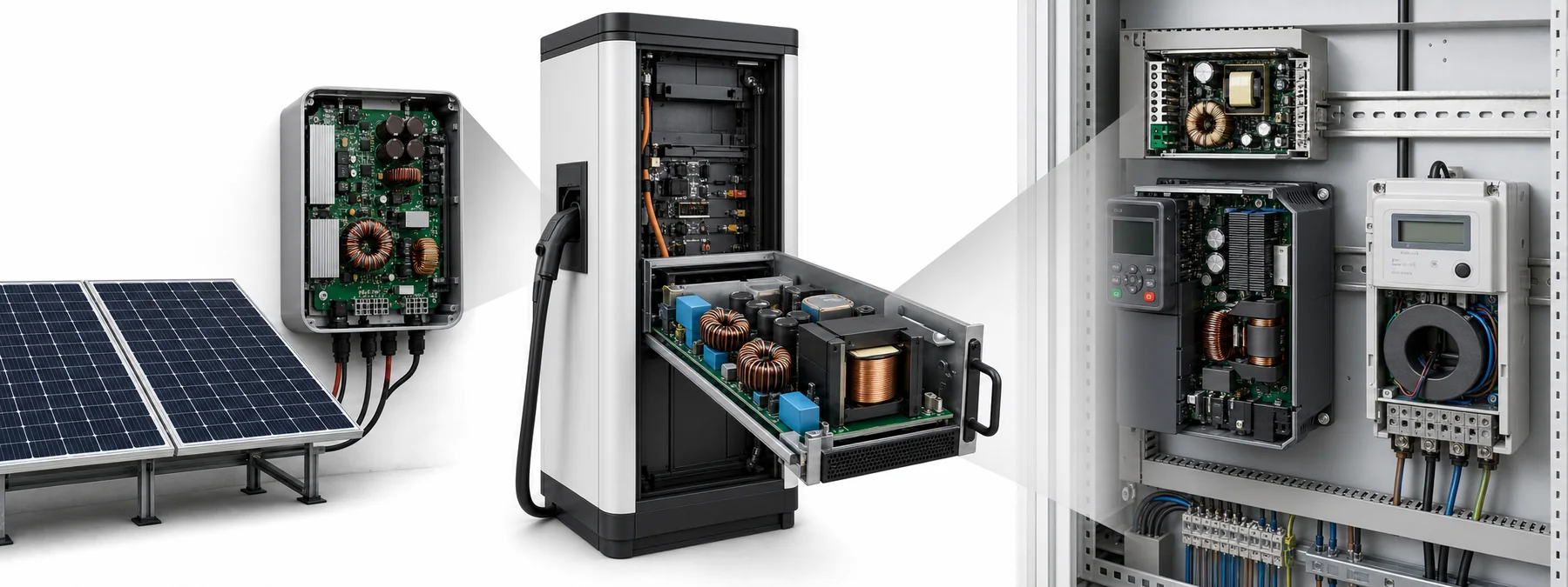
Applications: industry and energy, from sunlight to the grid
Solar inverters on the roof, DC chargers by the roadside, industrial power supplies, drives and meters in the switch cabinet — every turn in the flow of energy needs the right core.
Solar Charging-station Industrial Inverter Meters Solar inverters · MPPT Solar MPPT | 02 Boost: boost storage inductor.
Industrial power · forward Industrial and instrument power supplies | 05 Forward: forward transformer, output inductor.
Inverter drives · current feedback Inverter current feedback | 09 Signal transformers: current transformer.
Meters · current transformer Meter CTs | 09 Signal transformers: current transformer.
Charging-station PFC Front end of DC charging-station modules | 03 Boost PFC: PFC choke.
LLC Charging-station modules | 07 Half-bridge LLC: LLC main transformer, resonant inductor.
Boost converter — input inductor
The inductor sits on the input side and its average current equals the input current (larger than the output current); the worst case is at the lowest input voltage.
L Boost storage inductorCheck saturation at minimum input voltage and maximum load; adjust AL with the air gap CIRCUIT · BOOST Vin L S D C R Vo Band → material Band First choice Alternative Note ≦0.1 MHz TM82 — Bs 600 mT, gapped for DC bias 0.1–0.5 MHz TM71 — By IDC: μi 3800 + high Bs 0.5–0.8 MHz TM59★ — 0.8–3 MHz TM65★ TM61 ≦0.3 MHz — TM80 TM83★ When loss matters; high temperature (core up to 140 ℃) NiZn — — No TAK NiZn grade listed: high-current / high-flux designs use MnZn; for mA-level parts see SMD HF low-power inductors
Suggested shapes 3D · illustrative PQ Choose a series ▾ Strengths Optimized for switch-mode power: good ratio of volume, winding window and magnetic cross-section Center leg can be ground for an air gap to set AL Simple winding and assembly, good heat dissipation Trade-offs Higher core and bobbin cost Moderate shielding; less convenient to mount on the PCB 3D · illustrative RM Choose a series ▾ Strengths Saves PCB area; low height possible Encloses the winding: good shielding, good heat dissipation Center leg can be ground for an air gap to set AL Trade-offs Higher core cost Lead-out of thick wire is limited 3D · illustrative ER Choose a series ▾ Strengths Round center leg suits thick wire; lower winding loss Good heat dissipation, easy winding Trade-offs Weak self-shielding Moderate bobbin cost; less convenient to mount on the PCB 3D · illustrative Toroid T Choose a series ▾ Strengths Closed magnetic path without joints or air gap: highest magnetic efficiency Good self-shielding, low leakage flux Lowest core cost, no bobbin needed Trade-offs Winding must be threaded through the hole; high winding cost Less convenient to mount on the PCB No air gap; for storage inductors use a combination shape whose gap can be ground Where it goes AI data center
Backup-battery boost
New-energy vehicles
Storage inductors for 48 V mild-hybrid bidirectional DC/DC
Consumer · industrial
Solar MPPT, LED drivers, battery boost
Boost PFC — PFC choke
Rectified half-sine input with the duty cycle varying continuously over each mains cycle; check saturation at the peak current of the lowest mains voltage — choose by IDC, not by loss.
L PFC chokeHigh L, many turns; same material choice as the boost input inductor CIRCUIT · PFC ~ BR + L S D C R Vo Band → material Band First choice Alternative Note ≦0.1 MHz TM82 — Bs 600 mT, gapped for DC bias 0.1–0.5 MHz TM71 — By IDC: μi 3800 + high Bs 0.5–0.8 MHz TM59★ — 0.8–3 MHz TM65★ TM61 ≦0.3 MHz — TM80 TM83★ When loss matters; high temperature (core up to 140 ℃) NiZn — — No TAK NiZn grade listed: high-current / high-flux designs use MnZn; for mA-level parts see SMD HF low-power inductors
Powder-core toroids are also common for CCM PFC; ferrite has the advantage at higher frequencies or in CRM designs.
Suggested shapes 3D · illustrative PQ Choose a series ▾ Strengths Optimized for switch-mode power: good ratio of volume, winding window and magnetic cross-section Center leg can be ground for an air gap to set AL Simple winding and assembly, good heat dissipation Trade-offs Higher core and bobbin cost Moderate shielding; less convenient to mount on the PCB 3D · illustrative ER Choose a series ▾ Strengths Round center leg suits thick wire; lower winding loss Good heat dissipation, easy winding Trade-offs Weak self-shielding Moderate bobbin cost; less convenient to mount on the PCB 3D · illustrative U(PFC) Choose a series ▾ Strengths Large window, easy to wind thick wire Suits high-voltage insulation and high power Trade-offs Exposed winding, weak shielding Larger volume; mostly for PFC / high voltage / high power 3D · illustrative EE Choose a series ▾ Strengths Easiest bobbin winding and assembly Best heat dissipation Low core cost Trade-offs Weak self-shielding, higher leakage flux Needs a bobbin; for low height use EFD Where it goes AI data center
Front-end PFC in server and rack power supplies
New-energy vehicles
Front end of DC charging-station modules
Consumer · industrial
Adapters above 75 W, industrial power supplies, inverter appliances
Half-bridge LLC — transformer & resonant inductor
Lr–Cr–Lm resonance gives zero-voltage switching; the transformer sets Lm with its air gap, and Lr is often integrated as leakage inductance. Choose the material by operating frequency first.
Np/Ns LLC main transformer (gapped for Lm)The worst case is at the lowest operating frequency Lr Resonant inductorSame band as the main transformer; choose the material for that band CIRCUIT · LLC Vin S1 S2 Lr Cr Np Ns ×2 D1 D2 C R Vo Band → material Band First choice Alternative Note ≦0.3 MHz TM83★ TM80 TM81 TP40 TP44 TP45 0.3–1 MHz TM59★ TM50A TM65★ Only above 300 kHz 1–5 MHz TM63 TM61 First choice for small-size MHz transformers (lowest loss) NiZn — — No TAK NiZn grade listed: mainstream designs use MnZn; TAK has no 4F1-class NiZn power grade
Transformers ≤0.3 MHz: TM8x first, chosen by optimal operating temperature range (TP as alternates); >0.3 MHz: TM5x first.
Optimal operating temperature (℃): TM83★ 25–140, TM80 25–100, TM81 25–120, TM59★ 25–100, TM63 40–80.
Suggested shapes 3D · illustrative PQ Choose a series ▾ Strengths Optimized for switch-mode power: good ratio of volume, winding window and magnetic cross-section Center leg can be ground for an air gap to set AL Simple winding and assembly, good heat dissipation Trade-offs Higher core and bobbin cost Moderate shielding; less convenient to mount on the PCB 3D · illustrative ER / ER+I (planar) Choose a series ▾ Strengths Round center leg suits thick wire; lower winding loss Good heat dissipation, easy winding Trade-offs Weak self-shielding Moderate bobbin cost; less convenient to mount on the PCB 3D · illustrative EE/ETD Choose a series ▾ Strengths Easiest bobbin winding and assembly Best heat dissipation Low core cost Trade-offs Weak self-shielding, higher leakage flux Needs a bobbin; for low height use EFD 3D · illustrative RM(Lr) Choose a series ▾ Strengths Saves PCB area; low height possible Encloses the winding: good shielding, good heat dissipation Center leg can be ground for an air gap to set AL Trade-offs Higher core cost Lead-out of thick wire is limited Where it goes AI data center
Server PSU DC/DC stage; rack 800 V→50 V
New-energy vehicles
OBC (CLLC), high voltage to 12 V
Consumer · industrial
Charging-station modules, telecom power, TV power
Forward converter — transformer & output inductor
The transformer only transfers energy and does not store it, so a separate output inductor is used; with unipolar excitation, the remanence Br reduces the usable flux swing.
Np/Ns/Nr Forward transformerLow Br matters as much as high Bs; a reset winding is required L Output inductorSame material choice as the buck output inductor (by IDC) CIRCUIT · FORWARD Vin Dr Nr Np S Ns D1 L D2 C R Vo Band → material Band First choice Alternative Note Transformer ≤0.3 MHz TM80 TM81 TM83★ TP44 TP45 TP40 Transformer 0.3–0.5 MHz TM59★ TM50A TM5x first above 0.3 MHz Output inductor ≤0.1 MHz TM82 — Bs 600 mT, gapped for DC bias Output inductor 0.1–0.5 MHz TM71 — By IDC: μi 3800 + high Bs Output inductor 0.5–0.8 MHz TM59★ — Output inductor 0.8–3 MHz TM65★ TM61 Output inductor ≤0.3 MHz — TM80 TM83★ When loss matters; high temperature (core up to 140 ℃) NiZn — — Parts on this page are mainly MnZn; no TAK NiZn counterpart is listed; for mA-level small inductors see circuit 11
Transformers ≤0.3 MHz: TM8x first, chosen by optimal operating temperature range (TP as alternates); >0.3 MHz: TM5x first.
Optimal operating temperature (℃), forward transformer: TM80 25–100, TM81 25–120, TM83★ 25–140, TM59★ 25–100.
Suggested shapes 3D · illustrative EE/ETD Choose a series ▾ Strengths Easiest bobbin winding and assembly Best heat dissipation Low core cost Trade-offs Weak self-shielding, higher leakage flux Needs a bobbin; for low height use EFD 3D · illustrative PQ Choose a series ▾ Strengths Optimized for switch-mode power: good ratio of volume, winding window and magnetic cross-section Center leg can be ground for an air gap to set AL Simple winding and assembly, good heat dissipation Trade-offs Higher core and bobbin cost Moderate shielding; less convenient to mount on the PCB 3D · illustrative RM Choose a series ▾ Strengths Saves PCB area; low height possible Encloses the winding: good shielding, good heat dissipation Center leg can be ground for an air gap to set AL Trade-offs Higher core cost Lead-out of thick wire is limited 3D · illustrative Toroid T (inductor) Choose a series ▾ Strengths Closed magnetic path without joints or air gap: highest magnetic efficiency Good self-shielding, low leakage flux Lowest core cost, no bobbin needed Trade-offs Winding must be threaded through the hole; high winding cost Less convenient to mount on the PCB No air gap; for storage inductors use a combination shape whose gap can be ground Where it goes AI data center
Telecom / data-room DC/DC modules
New-energy vehicles
Medium-power auxiliary supplies
Consumer · industrial
Industrial and instrument power supplies
Signal transformers — wideband, balun, current transformer
One transformer circuit: the primary takes the signal source or a through-core current, the secondary drives the load. The brackets after each band give the scenario (signal/CT); MnZn high-permeability in the low bands, NiZn above 1 MHz.
T Wideband signal transformer / balunMnZn high-permeability up to 1.5 MHz, TM63 for 1–5 MHz; above that NiZn along the μi ladder CT Current transformersThe primary is often a single turn through the core; high μi and low remanence keep the magnetizing current small and the measurement accurate CIRCUIT · SIGNAL Vs Np Ns RL Band → material Band First choice Alternative Note ≤1.5 MHz (signal) T05 T10 E02 T12 MnZn high-perm, chosen by μi 1–5 MHz (signal) TM63 TM61 TM65★ Low-power wideband transformers with large signal swing / high bias ≦1.5 MHz(CT) T10 T07 T05 T06 E02 T2 1–5 MHz(CT) — TM63 MHz CTs (CT) ≤0.5 MHz (pulse/gate) TM71 T05 High μi and high Bs for ungapped pulse / gate-drive cores 1–5 MHz (pulse/gate) — TM63 MHz gate drive NiZn 1–2 MHz (signal) DL3 DL4 — Low-band baluns / wideband signal (catalogue frequency range) NiZn 1–3.5 MHz (signal) Q1C1 — Upper limit = lower of loss factor ≤2× its minimum and μ′ within 20 % of nominal NiZn 1–6.7 MHz (signal) M63 — NiZn 1–7.7 MHz (signal) M61 — NiZn 1–15 MHz (signal) — M61H NiZn 1–25 MHz (signal) M9A — NiZn 1–30 MHz (signal) V2F1 — NiZn 1–50 MHz (signal) — M5E1 Upper limit = lower of loss factor ≤2× its minimum and μ′ within 20 % of nominal NiZn 1–55 MHz (signal) — V4F1 NiZn (CT) — — No NiZn counterpart NiZn (pulse/gate) — — No NiZn counterpart
Suggested shapes 3D · illustrative Toroid T Choose a series ▾ Strengths Closed magnetic path without joints or air gap: highest magnetic efficiency Good self-shielding, low leakage flux Lowest core cost, no bobbin needed Trade-offs Winding must be threaded through the hole; high winding cost Less convenient to mount on the PCB No air gap; for storage inductors use a combination shape whose gap can be ground 3D · illustrative RH Choose a series ▾ Strengths Slips straight over a conductor or lead; no bobbin, simplest to fit For EMI suppression on cables/leads Trade-offs Mainly threaded onto a conductor, not used as a wound inductor The suppression band depends on the material; choose the grade by band 3D · illustrative EE Choose a series ▾ Strengths Easiest bobbin winding and assembly Best heat dissipation Low core cost Trade-offs Weak self-shielding, higher leakage flux Needs a bobbin; for low height use EFD 3D · illustrative UU Choose a series ▾ Strengths Large window, easy to wind thick wire Suits high-voltage insulation and high power Trade-offs Exposed winding, weak shielding Larger volume; mostly for PFC / high voltage / high power Where it goes AI data center
Networking signal transformers · Ethernet isolation · PSU current sensing
New-energy vehicles
In-vehicle communication isolation; current sensing in charging stations and OBCs
Consumer · industrial
Meter CTs, inverter current feedback, wideband baluns
Devices are generic illustrations, not specific products; "Where it sits" shows typical positions, not a specific customer's BOM.Materials by band: see each circuit page; verify under actual conditions.
Applications: networking, backup and wireless
Signal isolation and on-board power in network switches, backup conversion in UPS units, antennas in card readers and radios — signals, power and radio waves meet here.
Switches UPS RFID Antenna Switches Ethernet isolation Networking signal transformers · Ethernet isolation | 09 Signal transformers: wideband signal transformer.
on-board buck On-board buck in networking equipment | 01 Buck: output storage inductor.
power input AC input filter of every power supply | 08 Common-mode choke: common-mode choke.
UPS battery boost Backup-battery boost | 02 Boost: boost storage inductor.
low-frequency choke UPS low-frequency chokes | 11 Chokes & filters: low-frequency choke.
push-pull transformer UPS, battery-backup conversion | 06 Push-pull: push-pull transformer, output inductor.
RFID readers RFID readers | 10 Antenna & resonance: antenna, resonant inductor.
Antenna rods · high-Q inductors Radio antenna rods, high-Q inductors | 10 Antenna & resonance: antenna rod.
Signal transformers — wideband, balun, current transformer
One transformer circuit: the primary takes the signal source or a through-core current, the secondary drives the load. The brackets after each band give the scenario (signal/CT); MnZn high-permeability in the low bands, NiZn above 1 MHz.
T Wideband signal transformer / balunMnZn high-permeability up to 1.5 MHz, TM63 for 1–5 MHz; above that NiZn along the μi ladder CT Current transformersThe primary is often a single turn through the core; high μi and low remanence keep the magnetizing current small and the measurement accurate CIRCUIT · SIGNAL Vs Np Ns RL Band → material Band First choice Alternative Note ≤1.5 MHz (signal) T05 T10 E02 T12 MnZn high-perm, chosen by μi 1–5 MHz (signal) TM63 TM61 TM65★ Low-power wideband transformers with large signal swing / high bias ≦1.5 MHz(CT) T10 T07 T05 T06 E02 T2 1–5 MHz(CT) — TM63 MHz CTs (CT) ≤0.5 MHz (pulse/gate) TM71 T05 High μi and high Bs for ungapped pulse / gate-drive cores 1–5 MHz (pulse/gate) — TM63 MHz gate drive NiZn 1–2 MHz (signal) DL3 DL4 — Low-band baluns / wideband signal (catalogue frequency range) NiZn 1–3.5 MHz (signal) Q1C1 — Upper limit = lower of loss factor ≤2× its minimum and μ′ within 20 % of nominal NiZn 1–6.7 MHz (signal) M63 — NiZn 1–7.7 MHz (signal) M61 — NiZn 1–15 MHz (signal) — M61H NiZn 1–25 MHz (signal) M9A — NiZn 1–30 MHz (signal) V2F1 — NiZn 1–50 MHz (signal) — M5E1 Upper limit = lower of loss factor ≤2× its minimum and μ′ within 20 % of nominal NiZn 1–55 MHz (signal) — V4F1 NiZn (CT) — — No NiZn counterpart NiZn (pulse/gate) — — No NiZn counterpart
Suggested shapes 3D · illustrative Toroid T Choose a series ▾ Strengths Closed magnetic path without joints or air gap: highest magnetic efficiency Good self-shielding, low leakage flux Lowest core cost, no bobbin needed Trade-offs Winding must be threaded through the hole; high winding cost Less convenient to mount on the PCB No air gap; for storage inductors use a combination shape whose gap can be ground 3D · illustrative RH Choose a series ▾ Strengths Slips straight over a conductor or lead; no bobbin, simplest to fit For EMI suppression on cables/leads Trade-offs Mainly threaded onto a conductor, not used as a wound inductor The suppression band depends on the material; choose the grade by band 3D · illustrative EE Choose a series ▾ Strengths Easiest bobbin winding and assembly Best heat dissipation Low core cost Trade-offs Weak self-shielding, higher leakage flux Needs a bobbin; for low height use EFD 3D · illustrative UU Choose a series ▾ Strengths Large window, easy to wind thick wire Suits high-voltage insulation and high power Trade-offs Exposed winding, weak shielding Larger volume; mostly for PFC / high voltage / high power Where it goes AI data center
Networking signal transformers · Ethernet isolation · PSU current sensing
New-energy vehicles
In-vehicle communication isolation; current sensing in charging stations and OBCs
Consumer · industrial
Meter CTs, inverter current feedback, wideband baluns
Buck converter — output inductor
The inductor sits in series on the output side: large DC, small AC swing, so the design is governed by saturation (DC bias), not by core loss.
L Output storage inductorLook at hot Bs and the air gap first, then at loss; multiphase in parallel = VRM/TLVR CIRCUIT · BUCK Vin S L D C R Vo Band → material Band First choice Alternative Note Buck ≦0.1 MHz TM82 — Bs 600 mT, gapped for DC bias Buck 0.1–0.5 MHz TM71 — By IDC: μi 3800 + high Bs Buck 0.5–0.8 MHz TM59★ — Buck 0.8–3 MHz TM65★ TM61 TM63 Buck ≦0.3 MHz — TM80 TM83★ TP44 TP45 When loss matters; high temperature (core up to 140 ℃) VRM/TLVR ≦0.1 MHz TM82 — VRM/TLVR 0.1–0.5 MHz TM71 — VRM/TLVR 0.5–0.8 MHz TM59★ — VRM/TLVR 0.8–1 MHz TM65★ TM61 VRM/TLVR ≦0.3 MHz — TM80 TM83★ NiZn — — Parts on this page are mainly MnZn; no TAK NiZn counterpart is listed; for mA-level small inductors see circuit 11
Suggested shapes 3D · illustrative UD Choose a series ▾ Strengths Vertical mounting, small PCB footprint Suits high-current inductors with a single turn or copper-clip winding Withstands DC bias; switching frequencies of 0.7 MHz and above Trade-offs Taller Mainly for high-current VRM/TLVR use 3D · illustrative U+I Choose a series ▾ Strengths Horizontal U+I combination, low height Suits high-current inductors with a single turn or copper-clip winding Withstands DC bias; switching frequencies of 0.7 MHz and above Trade-offs Larger PCB footprint Two-piece assembly; AL consistency must be controlled 3D · illustrative SP+I Choose a series ▾ Strengths Excellent shielding, low leakage flux Easy PCB mounting, easy winding Combines with I/R/DR into low-leakage SMD inductors Trade-offs Weaker heat dissipation Two-piece assembly 3D · illustrative DR (NiZn, mA level) Choose a series ▾ Strengths Open magnetic circuit, withstands DC bias Simplest winding Can be paired with an SP/SRI shield cap to reduce leakage flux Trade-offs High leakage flux when used alone; watch EMI Inductance limited by the open magnetic circuit Where it goes AI data center
VRM and TLVR for GPUs/CPUs; on-board PoL
New-energy vehicles
ECU/ADAS processor power
Consumer · industrial
On-board buck on motherboards, networking and industrial-control boards
Common-mode choke — EMI filtering
Two windings in the same sense on one core: common-mode flux adds up to a high impedance, while the flux of the differential-mode operating current cancels. Choose the material by impedance vs. frequency.
L1/L2 Common-mode chokeChoose by the impedance peak in the band to be suppressed, not by inductance CIRCUIT · CMC L1 / L L2 / N N turns Icm → Icm → Band → material Band First choice Alternative Note ≦2 MHz T10 T12 T05 Tc >110 ℃, Bs 210 mT at 100 ℃ — leave margin when hot ≦30 MHz — E02 2–30 MHz overlap band NiZn 2–30 MHz L22A L28A SL50 SL80 G5A G5B NiZn 2–300 MHz L43 L8A L6A — Overlaps MnZn at 2–30 MHz; measured RH5 Z still rising at 300 MHz
2–30 MHz is the MnZn/NiZn overlap band: meet the low-frequency Z first, then keep the high-frequency Z as high as possible. For beads and sleeves see the last page, "EMI band overview".
Suggested shapes 3D · illustrative Toroid T Choose a series ▾ Strengths Closed magnetic path without joints or air gap: highest magnetic efficiency Good self-shielding, low leakage flux Lowest core cost, no bobbin needed Trade-offs Winding must be threaded through the hole; high winding cost Less convenient to mount on the PCB No air gap; for storage inductors use a combination shape whose gap can be ground 3D · illustrative UU/UT Choose a series ▾ Strengths Large window, easy to wind thick wire Suits high-voltage insulation and high power Trade-offs Exposed winding, weak shielding Larger volume; mostly for PFC / high voltage / high power 3D · illustrative RH bead Choose a series ▾ Strengths Slips straight over a conductor or lead; no bobbin, simplest to fit For EMI suppression on cables/leads Trade-offs Mainly threaded onto a conductor, not used as a wound inductor The suppression band depends on the material; choose the grade by band 3D · illustrative DR + plate Choose a series ▾ Strengths Open magnetic circuit, withstands DC bias Simplest winding Can be paired with an SP/SRI shield cap to reduce leakage flux Trade-offs High leakage flux when used alone; watch EMI Inductance limited by the open magnetic circuit Where it goes AI data center
AC input filter of every power supply
New-energy vehicles
In-vehicle CAN/Ethernet, high-voltage harness EMI
Consumer · industrial
Power inputs, USB/data cables
Boost converter — input inductor
The inductor sits on the input side and its average current equals the input current (larger than the output current); the worst case is at the lowest input voltage.
L Boost storage inductorCheck saturation at minimum input voltage and maximum load; adjust AL with the air gap CIRCUIT · BOOST Vin L S D C R Vo Band → material Band First choice Alternative Note ≦0.1 MHz TM82 — Bs 600 mT, gapped for DC bias 0.1–0.5 MHz TM71 — By IDC: μi 3800 + high Bs 0.5–0.8 MHz TM59★ — 0.8–3 MHz TM65★ TM61 ≦0.3 MHz — TM80 TM83★ When loss matters; high temperature (core up to 140 ℃) NiZn — — No TAK NiZn grade listed: high-current / high-flux designs use MnZn; for mA-level parts see SMD HF low-power inductors
Suggested shapes 3D · illustrative PQ Choose a series ▾ Strengths Optimized for switch-mode power: good ratio of volume, winding window and magnetic cross-section Center leg can be ground for an air gap to set AL Simple winding and assembly, good heat dissipation Trade-offs Higher core and bobbin cost Moderate shielding; less convenient to mount on the PCB 3D · illustrative RM Choose a series ▾ Strengths Saves PCB area; low height possible Encloses the winding: good shielding, good heat dissipation Center leg can be ground for an air gap to set AL Trade-offs Higher core cost Lead-out of thick wire is limited 3D · illustrative ER Choose a series ▾ Strengths Round center leg suits thick wire; lower winding loss Good heat dissipation, easy winding Trade-offs Weak self-shielding Moderate bobbin cost; less convenient to mount on the PCB 3D · illustrative Toroid T Choose a series ▾ Strengths Closed magnetic path without joints or air gap: highest magnetic efficiency Good self-shielding, low leakage flux Lowest core cost, no bobbin needed Trade-offs Winding must be threaded through the hole; high winding cost Less convenient to mount on the PCB No air gap; for storage inductors use a combination shape whose gap can be ground Where it goes AI data center
Backup-battery boost
New-energy vehicles
Storage inductors for 48 V mild-hybrid bidirectional DC/DC
Consumer · industrial
Solar MPPT, LED drivers, battery boost
CIRCUIT 11 · Chokes & filters — low-frequency chokes, SMD inductors, cost-effective grades Open circuit page → Chokes & filters — low-frequency chokes, SMD inductors, cost-effective grades
One series-inductor / LC-filter circuit, with the material chosen by scenario (shown in brackets after the band): MnZn high-Bs for ≤0.1 MHz low-frequency chokes; solder-heat-resistant NiZn for mA-level SMD inductors; Mg-based grades for cost-driven filters and beads.
L Low-frequency choke / ballast inductor≤0.1 MHz; high Bs, including saturable reactors and magnetic amplifiers L SMD small inductor / filter inductormA level, solder-heat resistant, miniaturized; rated current is set by size and heat CIRCUIT · FILTER Vin L C C IC Band → material Band First choice Alternative Note ≤0.1 MHz (low-frequency choke) T2 T2M TB2 — Magnetic amplifiers / saturable reactors / DC-biased chokes (Bs 580 / 460 mT) NiZn (low-frequency choke) — — No NiZn counterpart NiZn ≤2 MHz (SMD small inductor) DL3 DL4 — mA-level SMD; loss-factor minimum 0.2 MHz NiZn ≤2.5 MHz (SMD small inductor) G5A G5B — mA-level SMD; loss-factor minimum 0.1 MHz NiZn ≤3 MHz (SMD small inductor) DL5H — NiZn ≤3.5 MHz (SMD small inductor) DL5 — NiZn ≤3.6 MHz (SMD small inductor) DL6 — Mg-based ≤1.2 MHz (economy) MF3 — RFID coils / wideband suppression rings Mg-based ≤2 MHz (economy) MG2 — Standard chokes / low-mid-frequency filters Mg-based ≤3.5 MHz (economy) MGB1 — Wideband EMI beads / mid-high-frequency filter inductors, Bs 380 / 320 mT Mg-based 0.1–0.7 MHz (economy) MF2 — Large mains-input CM chokes / cable rings; Tc >130 ℃, Bs 95 mT at 100 ℃ — room-temperature use only Mg-based 0.1–1.4 MHz (economy) MF1 — RF / IF filters, resonant inductors (μ180)
Suggested shapes 3D · illustrative EE (low-frequency choke) Choose a series ▾ Strengths Easiest bobbin winding and assembly Best heat dissipation Low core cost Trade-offs Weak self-shielding, higher leakage flux Needs a bobbin; for low height use EFD 3D · illustrative DR drum core Choose a series ▾ Strengths Open magnetic circuit, withstands DC bias Simplest winding Can be paired with an SP/SRI shield cap to reduce leakage flux Trade-offs High leakage flux when used alone; watch EMI Inductance limited by the open magnetic circuit 3D · illustrative RH bead Choose a series ▾ Strengths Slips straight over a conductor or lead; no bobbin, simplest to fit For EMI suppression on cables/leads Trade-offs Mainly threaded onto a conductor, not used as a wound inductor The suppression band depends on the material; choose the grade by band 3D · illustrative Toroid T Choose a series ▾ Strengths Closed magnetic path without joints or air gap: highest magnetic efficiency Good self-shielding, low leakage flux Lowest core cost, no bobbin needed Trade-offs Winding must be threaded through the hole; high winding cost Less convenient to mount on the PCB No air gap; for storage inductors use a combination shape whose gap can be ground Where it goes AI data center
UPS low-frequency chokes; motherboard power-rail filtering
New-energy vehicles
Sensor and ECU power filtering
Consumer · industrial
Lighting ballasts; phone/wearable power rails, USB-cable EMI
Push-pull converter — centre-tapped transformer
Two switches conduct alternately and excite the core symmetrically in both directions; more power per core size than unipolar topologies, but margin must be left for flux walking.
Np×2/Ns×2 Push-pull transformerBipolar excitation; ideally no DC, in practice leave margin for flux walking L Output inductorRipple frequency 2·fsw; same material choice as the buck output inductor CIRCUIT · PUSHPULL Vin Np ×2 S1 S2 Ns ×2 D1 D2 L C R Vo Band → material Band First choice Alternative Note Transformer ≤0.3 MHz TM80 TM81 TM83★ TP44 TP45 TP40 Transformer 0.3–0.5 MHz TM59★ TM50A TM5x first above 0.3 MHz Output inductor ≤0.1 MHz TM82 — Bs 600 mT, gapped for DC bias Output inductor 0.1–0.5 MHz TM71 — By IDC: μi 3800 + high Bs Output inductor 0.5–0.8 MHz TM59★ — Output inductor 0.8–3 MHz TM65★ TM61 Output inductor ≤0.3 MHz — TM80 TM83★ When loss matters; high temperature (core up to 140 ℃) NiZn — — Parts on this page are mainly MnZn; no TAK NiZn counterpart is listed; for mA-level small inductors see circuit 11
Transformers ≤0.3 MHz: TM8x first, chosen by optimal operating temperature range (TP as alternates); >0.3 MHz: TM5x first.
Optimal operating temperature (℃), push-pull transformer: TM80 25–100, TM81 25–120, TM83★ 25–140, TM59★ 25–100.
Suggested shapes 3D · illustrative EE/EP Choose a series ▾ Strengths Easiest bobbin winding and assembly Best heat dissipation Low core cost Trade-offs Weak self-shielding, higher leakage flux Needs a bobbin; for low height use EFD 3D · illustrative RM Choose a series ▾ Strengths Saves PCB area; low height possible Encloses the winding: good shielding, good heat dissipation Center leg can be ground for an air gap to set AL Trade-offs Higher core cost Lead-out of thick wire is limited 3D · illustrative Toroid T Choose a series ▾ Strengths Closed magnetic path without joints or air gap: highest magnetic efficiency Good self-shielding, low leakage flux Lowest core cost, no bobbin needed Trade-offs Winding must be threaded through the hole; high winding cost Less convenient to mount on the PCB No air gap; for storage inductors use a combination shape whose gap can be ground 3D · illustrative PQ Choose a series ▾ Strengths Optimized for switch-mode power: good ratio of volume, winding window and magnetic cross-section Center leg can be ground for an air gap to set AL Simple winding and assembly, good heat dissipation Trade-offs Higher core and bobbin cost Moderate shielding; less convenient to mount on the PCB Where it goes AI data center
UPS, battery-backup conversion
New-energy vehicles
Isolated gate-drive supplies for traction inverters
Consumer · industrial
12/24 V low-voltage input converters, inverters
Antenna & resonance — antenna rods, RFID, high-Q inductors
Antenna rods and high-Q inductors are open magnetic circuits; the high resistivity of NiZn keeps them low-loss and stable into the MHz range. Each grade has its own high-Q band (around the minimum of its loss factor); choose along the μi ladder by operating frequency.
L Antenna rod / resonant inductorOpen magnetic circuit; choose by Q and temperature stability; M9A/V2F1 for 13.56 MHz NFC CIRCUIT · ANTENNA IC L rod C Ant. Band → material Band First choice Alternative Note NiZn 0.1–2.2 MHz Q1C1 — μi 10–250; high-Q band = loss factor ≤1.5× its minimum NiZn 0.2–4.1 MHz M63 — NiZn 0.2–6.2 MHz M61 — NiZn 0.5–9.8 MHz M61H — NiZn 0.8–25 MHz M9A — NiZn 1–30 MHz V2F1 — NiZn 2–50 MHz — M5E1 μi 10–250; high-Q band = loss factor ≤1.5× its minimum NiZn 3–55 MHz — V4F1
Suggested shapes 3D · illustrative R antenna rod Choose a series ▾ Strengths Open magnetic circuit, suited to sending and receiving magnetic fields (antennas, sensing, tuning) Simplest structure, easy winding Trade-offs High leakage flux; watch EMI Inductance limited by the open magnetic circuit 3D · illustrative Toroid T Choose a series ▾ Strengths Closed magnetic path without joints or air gap: highest magnetic efficiency Good self-shielding, low leakage flux Lowest core cost, no bobbin needed Trade-offs Winding must be threaded through the hole; high winding cost Less convenient to mount on the PCB No air gap; for storage inductors use a combination shape whose gap can be ground 3D · illustrative RH Choose a series ▾ Strengths Slips straight over a conductor or lead; no bobbin, simplest to fit For EMI suppression on cables/leads Trade-offs Mainly threaded onto a conductor, not used as a wound inductor The suppression band depends on the material; choose the grade by band 3D · illustrative DR Choose a series ▾ Strengths Open magnetic circuit, withstands DC bias Simplest winding Can be paired with an SP/SRI shield cap to reduce leakage flux Trade-offs High leakage flux when used alone; watch EMI Inductance limited by the open magnetic circuit Where it goes AI data center
Matching inductors for RF and wireless modules
New-energy vehicles
Automotive RF, keyless-entry antennas
Consumer · industrial
RFID readers, radio antenna rods, high-Q inductors
Devices are generic illustrations, not specific products; "Where it sits" shows typical positions, not a specific customer's BOM.Materials by band: see each circuit page; verify under actual conditions.
Material family positioning
MnZn combines high permeability and saturation flux density with low resistivity — the mainstay of power transformers and inductors, divided by frequency into four bands: conventional low-frequency, mid-frequency, mid-high-frequency and high-frequency. High-Bs special power grades are made for high-current inductors, and high-permeability grades guard common-mode filtering and signals.
NiZn's high resistivity comes into its own in MHz-range small inductors, EMI suppression and high-Q applications.
Frequency decides the family first; within the family, the grade is chosen by temperature and flux.
Family Group Grades Frequency Typical uses MnZn Conventional low-frequency power T2 ・T2M ・TB2 ≦0.1 MHz Low-frequency supplies · ballasts · baluns Mid-frequency power TP40 ・TP44 ・TP45 ・TM80 ・TM81 ・TM83★ 0.1–0.3 MHz Switch-mode / LLC transformers · wide-temperature power supplies Mid/high-frequency power TM50A ・TM59★ 0.3–0.7 MHz LLC/resonant transformers · server power High-frequency power TM61 ・TM65★ ・TM63 >0.7 MHz GaN/SiC MHz-class transformers · VRM/TLVR High-Bs special power TM71 ・TM82 TM71 ≦0.5・TM82 ≦0.2 MHzPFC chokes · high-current storage inductors · pulse/gate-drive transformers High permeability / EMI suppression E02 ・T05 ・T06 ・T07 ・T10 ・T12 ・ME03★ Common mode ≤2 MHz; ME03★ 30–1000 MHz Wideband signal · current transformers · common-mode filtering · EMI beads/sleeves NiZn High flux, thermal-shock resistant DL3 ・DL4 ・DL5 ・DL6 ・DL5H Inductors ≦2–3.6 MHz mA-level SMD small inductors · solder-heat resistant Wide-temperature stable SL50 ・SL80 EMI 2–30 MHz EMI for wide-temperature applications (low temperature coefficient) High-permeability, high-flux EMI G5A ・G5B Inductors ≦2.5 MHz · EMI to ~1 GHz mA-level SMD small inductors · EMI parts carrying bias current High-permeability EMI L43 ・L6A ・L8A ・L22A ・L28A Inductors ≦0.5–1 MHz · EMI to ~1 GHz EMI suppression (L43 · L6A , wideband) NiMgZn MGB1 ・MG2 ・MF1 ・MF2 ・MF3 ≦1.2–3.5 MHz Economy inductors · EMI High-frequency stable (high Q) V4F1 –Q1C1 (μi 10–250)approx. 0.1–30 MHz (high Q) High-Q inductors · RFID · antenna rods · wideband baluns
MnZn Conventional low-frequency, mid-frequency, mid-high-frequency and high-frequency power grades, high-Bs special power grades, and high-permeability / EMI-suppression grades.
→ NiZn High-flux thermal-shock-resistant, wide-temperature stable, high-permeability high-flux EMI, high-permeability EMI, NiMgZn, and high-frequency stable (high-Q) grades.
→ FeNi iron-nickel alloy cores (from 2026) Alloy materials are sourced strategically; TAK carries out product development and manufacturing, extending into applications that need higher saturation flux density and higher current.
Family-level orientation; the application frequency is assessed by flux, temperature and the individual grade's specification.★ = 2027 new material.
 TAK Technology
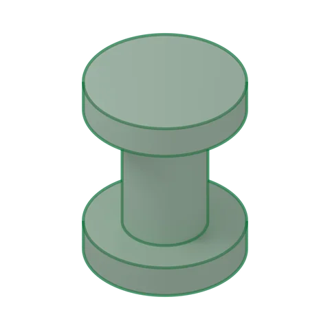
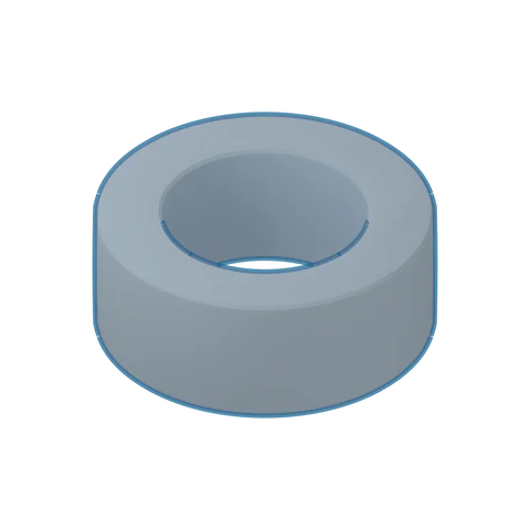 3D · illustrativeToroid TChoose a series ▾
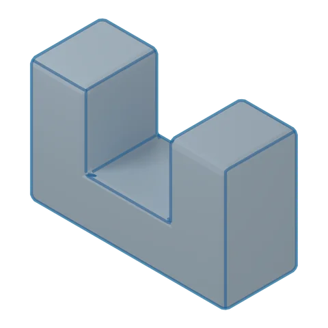 3D · illustrativeUU/UTChoose a series ▾
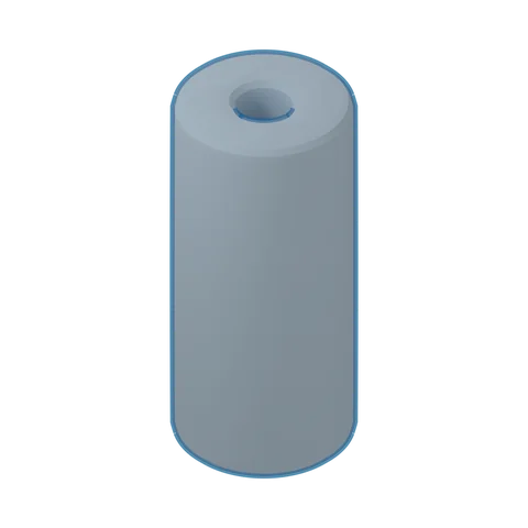 3D · illustrativeRH beadChoose a series ▾
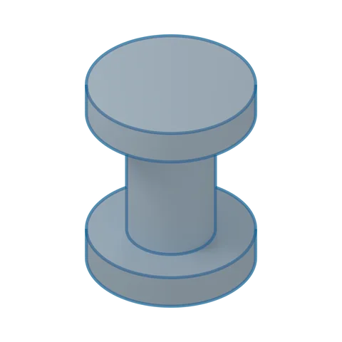 3D · illustrativeDR + plateChoose a series ▾
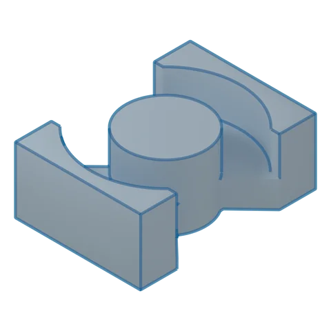 3D · illustrativePQChoose a series ▾
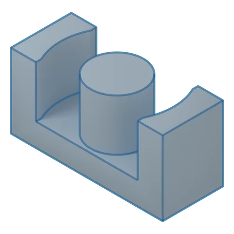 3D · illustrativeER / ER+I (planar)Choose a series ▾
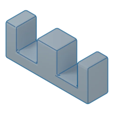 3D · illustrativeEE/ETDChoose a series ▾
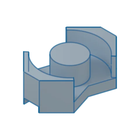 3D · illustrativeRM(Lr)Choose a series ▾
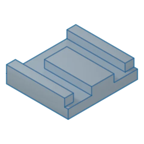 3D · illustrativeUDChoose a series ▾
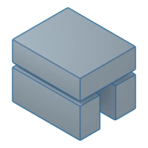 3D · illustrativeU+IChoose a series ▾
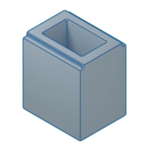 3D · illustrativeSP+IChoose a series ▾