TAK Technology
Soft ferrite · NiZn & MnZn
From formulation to core
TAK / Company profile 2027
06 / Catalogue
Materials

All grades

TTechnology
AAssurance
KKeeper

MnZn Power Ferrite · Mid-frequency power · Material specification

TP44

LOW-LOSS POWER FERRITE

SMPS Main TransformerLED DriverIndustrial PowerAdapter

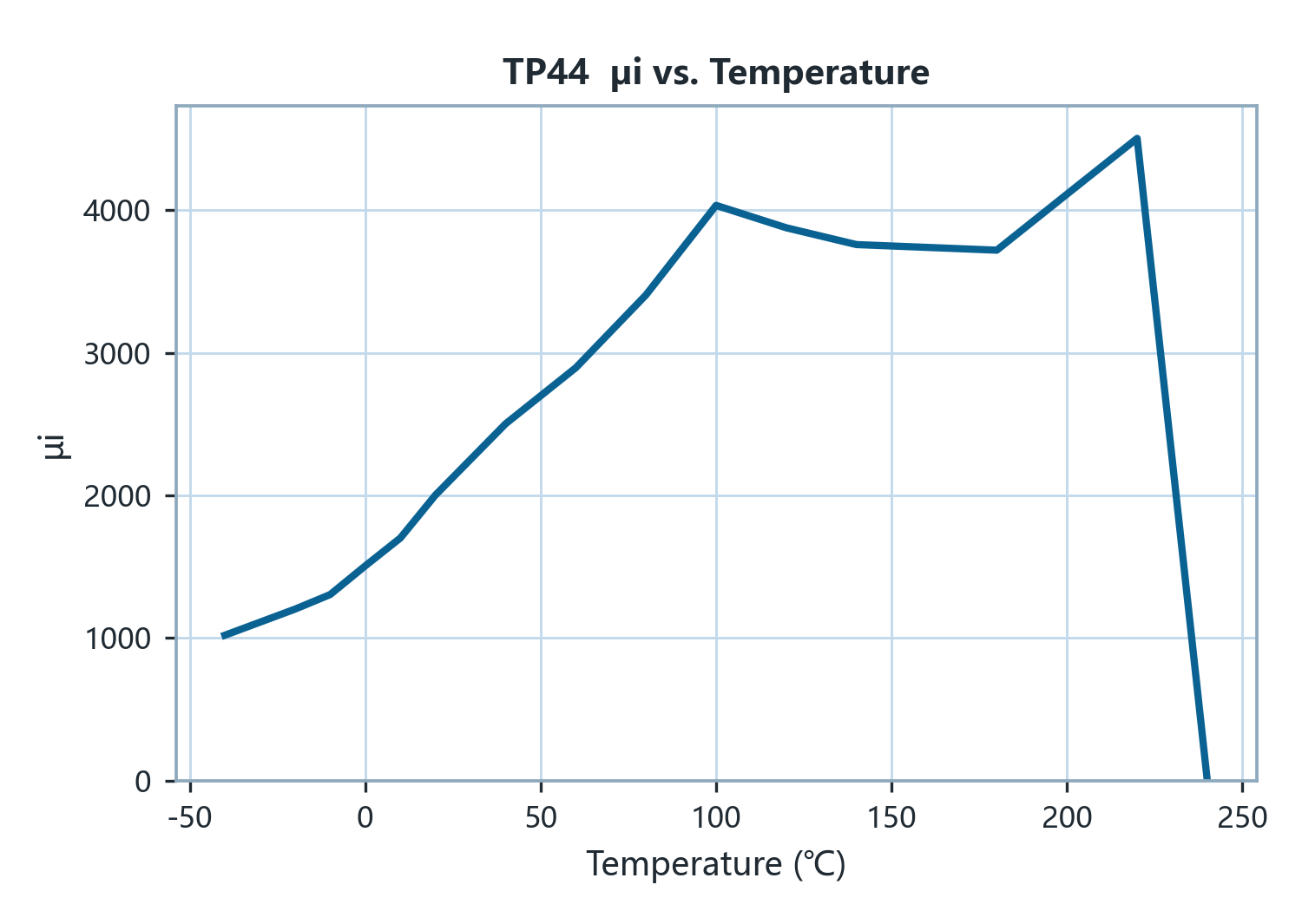
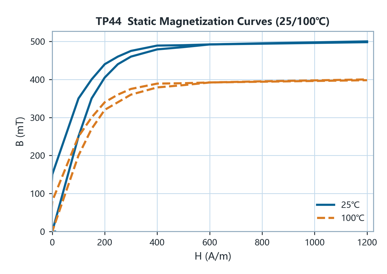
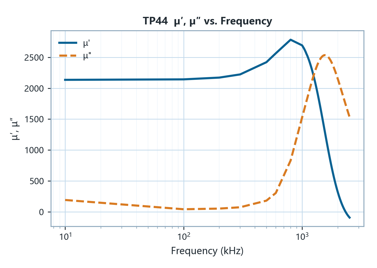
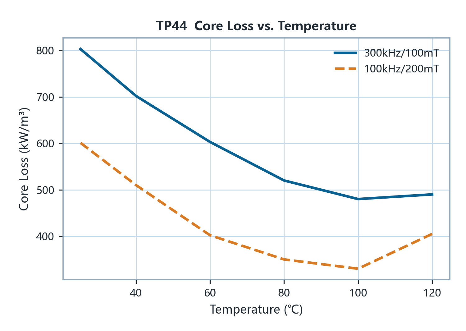
TP44 is a low-loss MnZn power ferrite with an initial permeability (μi) of 2000, a saturation flux density (Bs) of 500 mT at 25 °C (400 mT at 100 °C) and a Curie temperature above 220 °C. Its advantage is concentrated in the 100 kHz high-flux region: Pcv at 100 kHz / 200 mT is 600 kW/m³ at 25 °C and 330 kW/m³ at 100 °C, about 30 % below TP40's 480 kW/m³, and at 25 kHz / 200 mT it is 50 kW/m³ at 100 °C; at 100 °C the remanence (Br) is 80 mT and the coercivity (Hc) 8 A/m, and the relative loss factor at 100 kHz is below 5×10⁻⁶, the lowest of the three TP grades. At 300 kHz / 100 mT it reads 800 → 500 kW/m³, above TP40's 400 kW/m³, so its optimum band is 100–200 kHz. Typical applications are 100–200 kHz switch-mode main transformers, LED drivers, industrial supplies and adapters. Among the six mid-frequency grades TP44 is the low-loss variant of the TP family for the 100 kHz region; with the same μi as TP40 it can be substituted without changing the number of turns. TP40 or TP45 are more appropriate for operating points near 300 kHz; TP45 (μi 2500, equivalent loss at 100 kHz / 200 mT) is recommended where fewer turns are required.

Magnetic Characteristics

CharacteristicCondition25 ℃100 ℃Unit
Initial Permeability μiInitial Permeability μi100 kHz & <0.2 mT2000±25%——
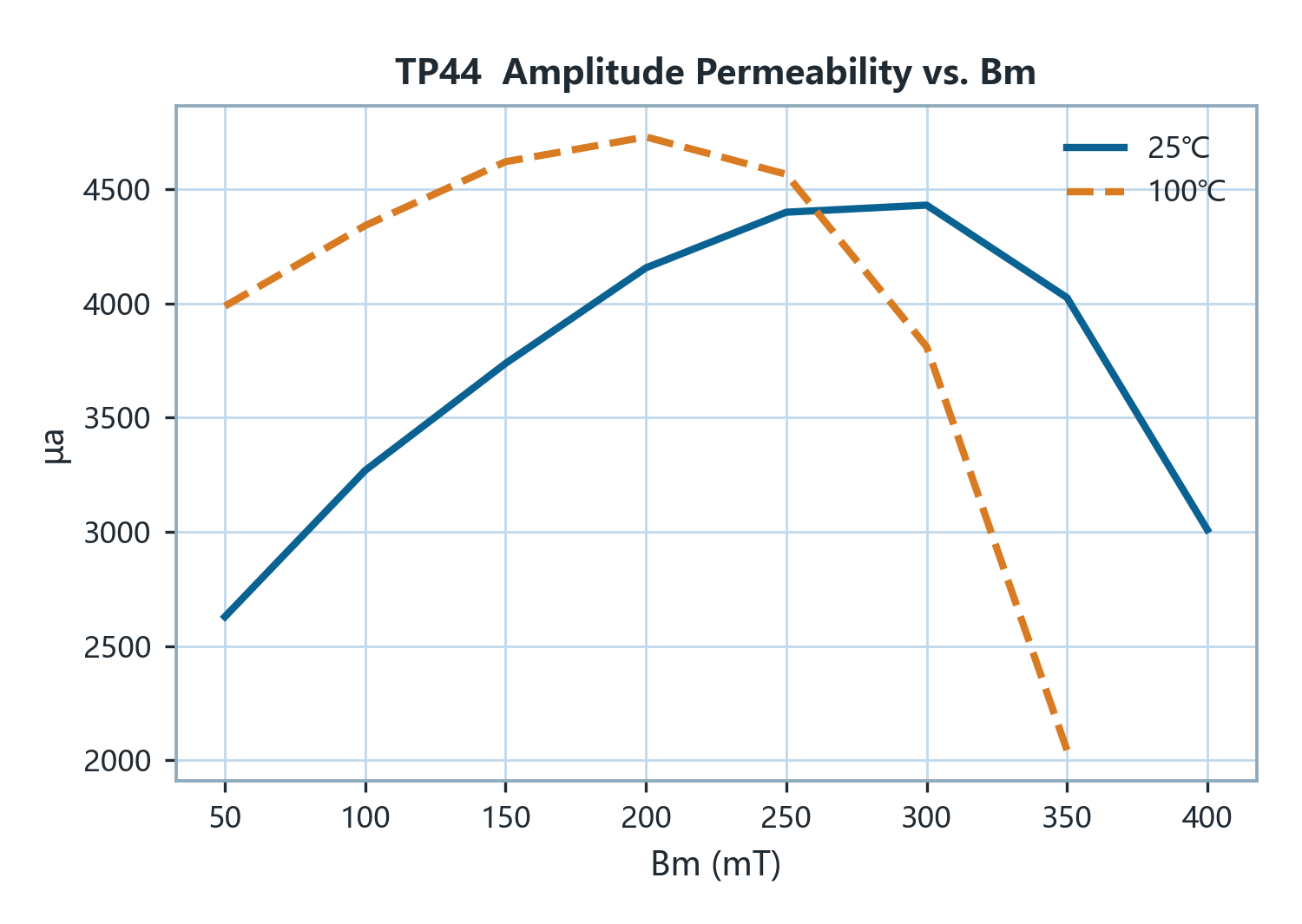
Amplitude Permeability μaAmplitude Permeability μa25 kHz/400 mT> 3000> 2700—
Saturation Flux Density BsSaturation Flux Density Bs1200 A/m 100 Hz500400mT
Remanence BrRemanence Br1200 A/m 100 Hz15080mT
Coercivity HcCoercivity Hc1200 A/m 100 Hz128A/m
Loss FactorLoss Factor100 kHz & <0.2 mT< 5—10⁻⁶
Curie Temperature TcCurie Temperature Tc100 kHz & <0.2 mT>220—℃
Density DDensity DArchimedes method4.8—g/cm³
Electrical Resistivity ρElectrical Resistivity ρDC Current>6.5—Ω·m

Power Loss · kW/m³

Condition25 ℃100 ℃
25 kHz/200 mT12050
100 kHz/200 mT600330
300 kHz/100 mT800500

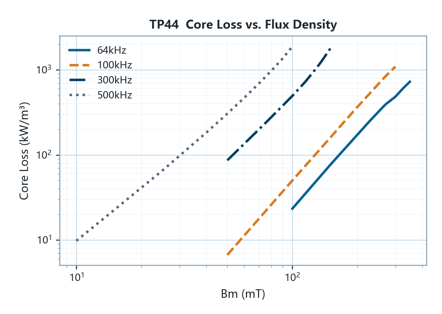
Pcv = K·f^α·B^β

RangeKαβ
100 ≤5006.64E-081.951322.55001

Characteristic curves

CURVE 01curve
CURVE 02curve
CURVE 03curve
CURVE 04curve
CURVE 05curve
CURVE 06curve

Applications

ApplicationRoleBandTemperature
Flyback transformer (>150 W)Alternative≤0.3 MHz80–100 ℃
Forward transformerAlternative≤0.3 MHz80–100 ℃
Push-pull transformerAlternative≤0.3 MHz80–100 ℃
LLC / resonant & bridge transformer (incl. Lr)Alternative≤0.3 MHz80–100 ℃
Buck output inductorAlternative≤0.3 MHz80–100 ℃

Used in circuits

Overview ⤢ ←→Switch chapter · EscBack to overview