 TAK Technology
TM65★ 2027 NEW
HIGH-FREQUENCY INDUCTOR POWER FERRITE
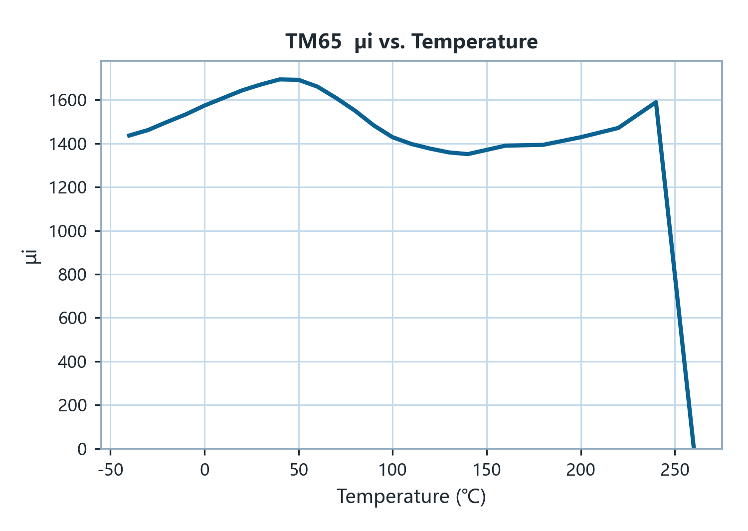
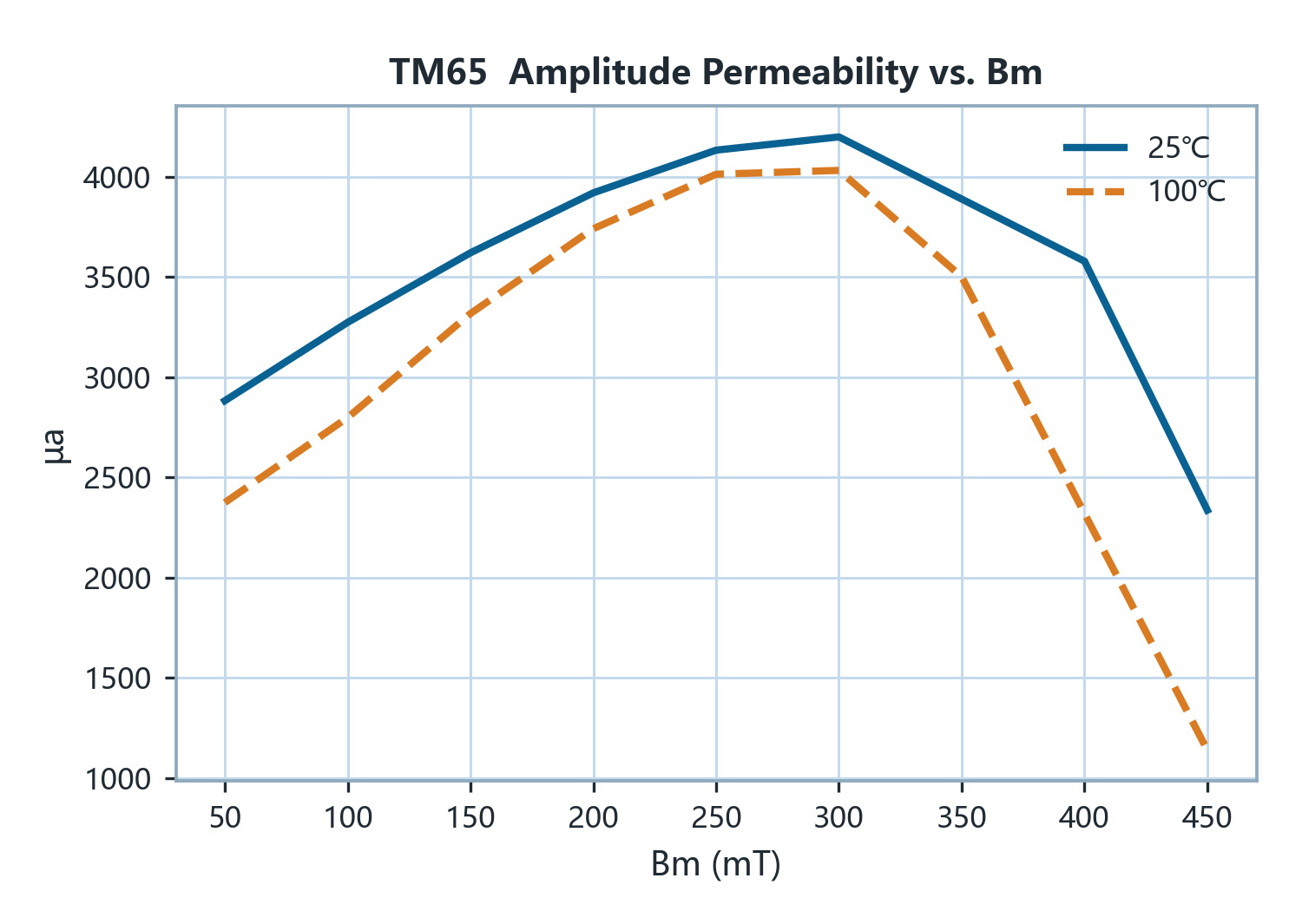
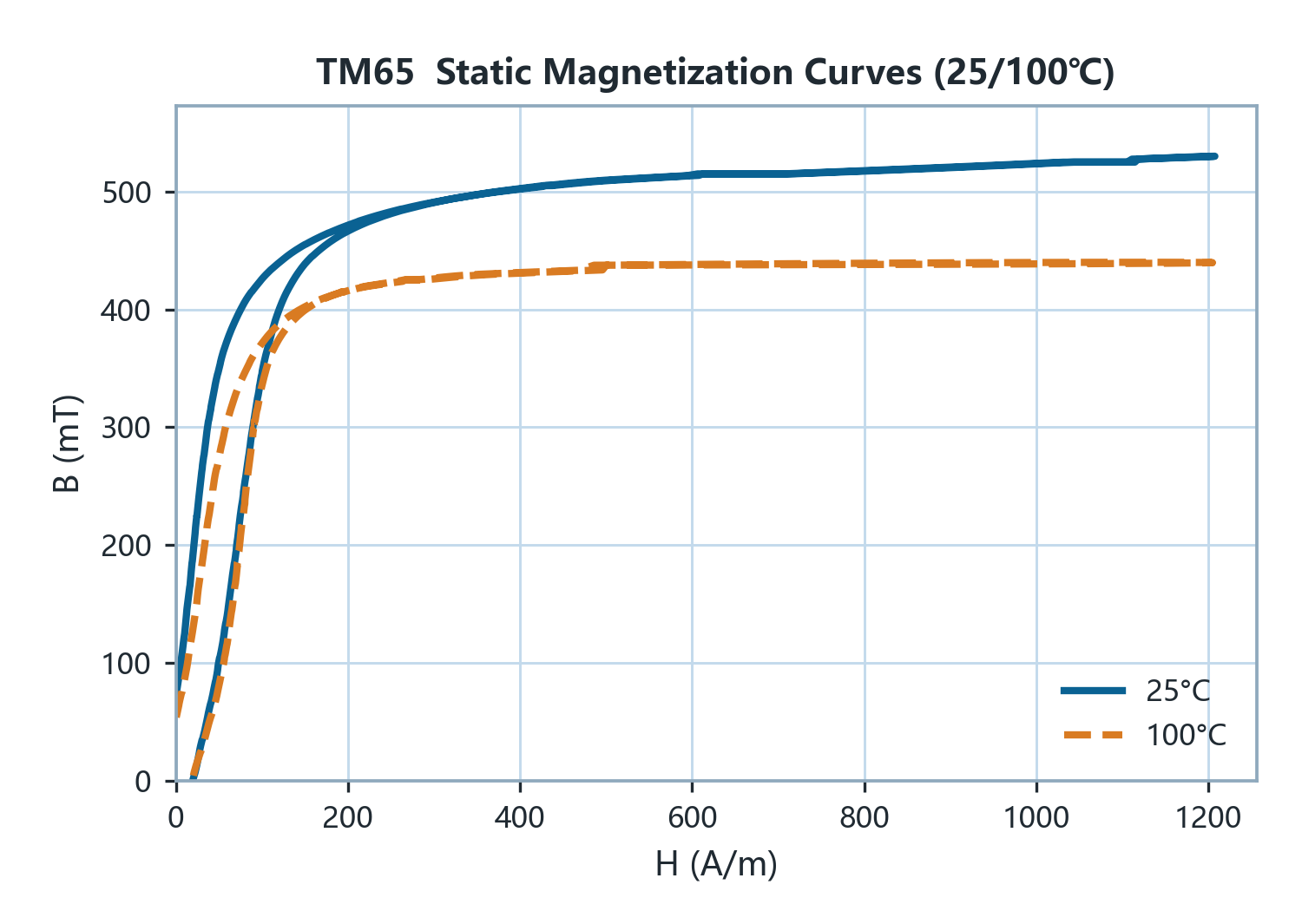
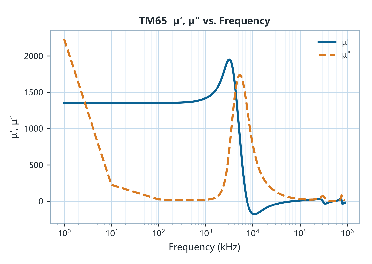
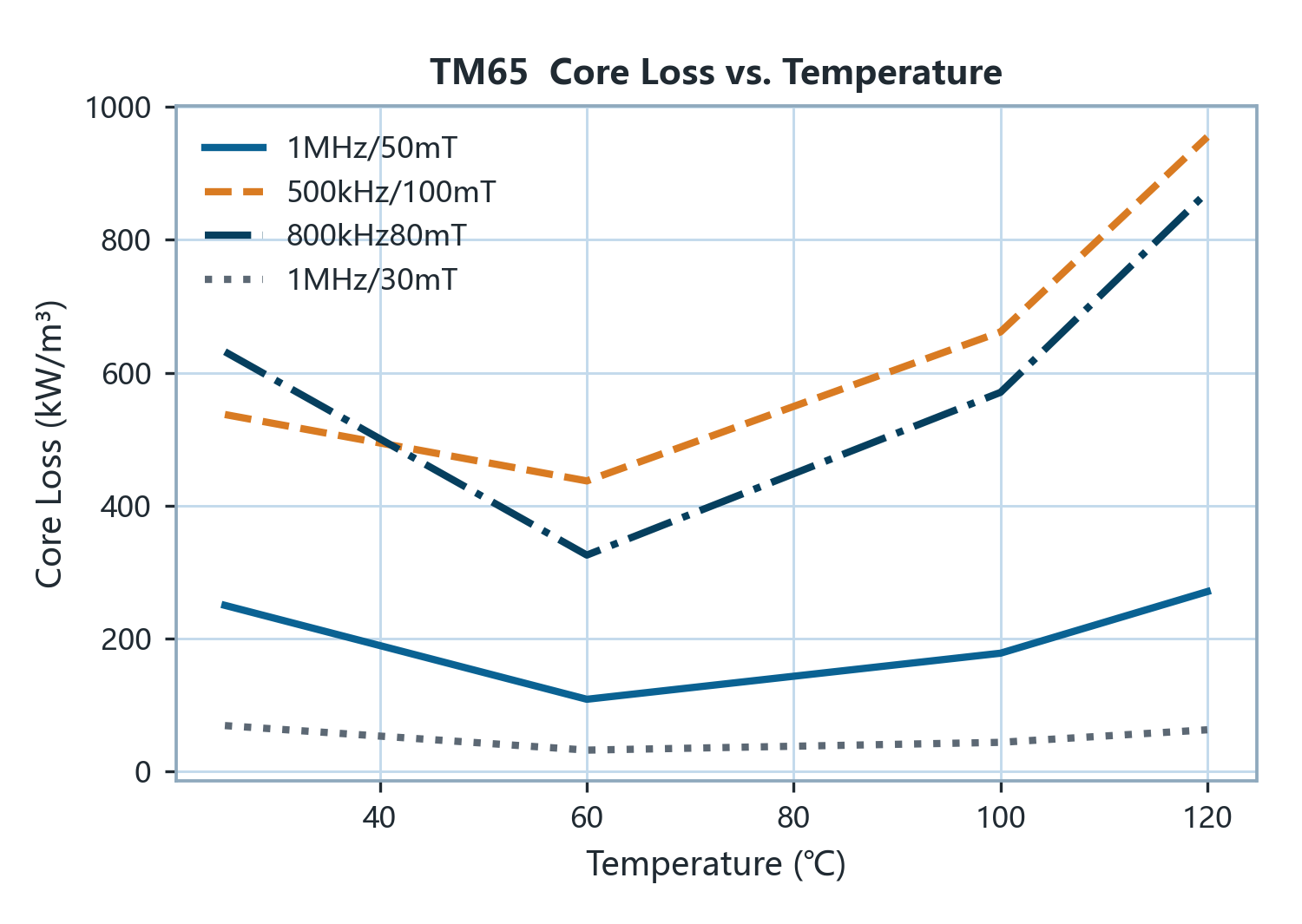
TM65 is a high-frequency inductor MnZn power ferrite with an initial permeability (μi) of 1300, the highest of the high-frequency power grades, a saturation flux density (Bs) of 540 mT at 25 °C (440 mT at 100 °C) and a Curie temperature above 240 °C. Its loss minimum lies at operating temperature: Pcv at 1 MHz / 50 mT decreases from 250 kW/m³ at 25 °C to 180 kW/m³ at 100 °C, at 800 kHz / 60 mT it is 300 → 220 kW/m³ and at 1 MHz / 30 mT 70 → 50 kW/m³; the remanence (Br) at 100 °C is 50 mT. In the DC-bias measurement of eight grades on the same UD core, its 100 °C I@90 % reaches 47.3 A in the 220 nH band, equivalent to TM59 with lower high-frequency loss, meeting the requirements of single-turn high-current MHz-class inductors. Typical applications are VRM and TLVR inductors for CPU/GPU power, POL high-frequency inductors, and 1 MHz-class DC-DC inductors and transformers. Among the high-frequency grades TM65 is the recommended inductor grade for new designs (TM61 is the earlier generation, retained for existing designs and still applicable to 1–3 MHz transformers); small-size MHz transformers should use TM63. At 500 kHz / 100 mT it reads 600 → 630 kW/m³, so large-flux transformers below 700 kHz remain the domain of TM59.
Magnetic Characteristics
| Characteristic | Condition | 25 ℃ | 100 ℃ | Unit |
|---|---|---|---|---|
| Initial Permeability μiInitial Permeability μi | 100 kHz & <0.2 mT | 1300±25% | — | — |
| Amplitude Permeability μaAmplitude Permeability μa | 25 kHz/400 mT | > 2400 | > 2400 | — |
| Saturation Flux Density BsSaturation Flux Density Bs | 1200 A/m 100 Hz | 540 | 440 | mT |
| Remanence BrRemanence Br | 1200 A/m 100 Hz | 70 | 50 | mT |
| Coercivity HcCoercivity Hc | 1200 A/m 100 Hz | 15 | 20 | A/m |
| Loss FactorLoss Factor | 100 kHz & <0.2 mT | <15 | — | 10⁻⁶ |
| Curie Temperature TcCurie Temperature Tc | 100 kHz & <0.2 mT | >240 | — | ℃ |
| Density DDensity D | Archimedes method | >4.85 | — | g/cm³ |
| Electrical Resistivity ρElectrical Resistivity ρ | DC Current | >10 | — | Ω·m |
Power Loss · kW/m³
| Condition | 25 ℃ | 100 ℃ | Condition | 25 ℃ | 100 ℃ |
|---|---|---|---|---|---|
| 500 kHz/50 mT | 70 | 50 | 800 kHz/80 mT | 650 | 600 |
| 500 kHz/100 mT | 600 | 630 | 1 MHz/30 mT | 70 | 50 |
| 800 kHz/60 mT | 300 | 220 | 1 MHz/50 mT | 250 | 180 |
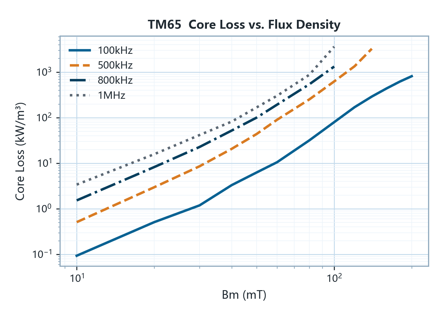
Pcv = K·f^α·B^β
| Range | K | α | β |
|---|---|---|---|
| 100 ≤500 | 5.064E-09 | 1.3197 | 3.7683 |
| 100 ≤1000 | 1.313E-10 | 1.7771 | 3.9893 |
| 100 ≤3000 | 2.212E-13 | 2.7658 | 3.8768 |
Characteristic curves
Applications
| Application | Role | Band | Temperature |
|---|---|---|---|
| Flyback transformer (>150 W) | Alternative | 0.7–1 MHz | 40–80 ℃ |
| Flyback transformer (≤150 W, by IDC) | First choice | 0.8–3 MHz | — |
| LLC / resonant & bridge transformer (incl. Lr) | Alternative | 0.7–1 MHz | 40–80 ℃ |
| Small-size MHz transformer (1–5 MHz) | Alternative | 1–3 MHz | 40–80 ℃ |
| Buck output inductor | First choice | 0.8–3 MHz | — |
| Boost input inductor | First choice | 0.8–3 MHz | — |
| PFC chokes & high-current storage inductors | First choice | 0.8–3 MHz | — |
| Forward / push-pull output inductor | First choice | 0.8–3 MHz | — |
| VRM / TLVR / PoL inductor | First choice | 0.8–1 MHz | — |
| Wideband signal transformer / balun | Alternative | 1–3 MHz | — |