 TAK Technology
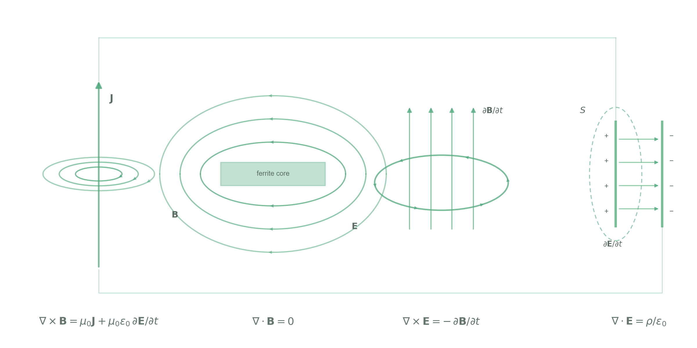
Push-pull converter — centre-tapped transformer
Two switches conduct alternately and excite the core symmetrically in both directions; more power per core size than unipolar topologies, but margin must be left for flux walking.
- Np×2/Ns×2Push-pull transformerBipolar excitation; ideally no DC, in practice leave margin for flux walking
- LOutput inductorRipple frequency 2·fsw; same material choice as the buck output inductor
Band → material
| Band | First choice | Alternative | Note |
|---|---|---|---|
| Transformer ≤0.3 MHz | TM80TM81TM83★ | TP44TP45TP40 | |
| Transformer 0.3–0.5 MHz | TM59★ | TM50A | TM5x first above 0.3 MHz |
| Output inductor ≤0.1 MHz | TM82 | — | Bs 600 mT, gapped for DC bias |
| Output inductor 0.1–0.5 MHz | TM71 | — | By IDC: μi 3800 + high Bs |
| Output inductor 0.5–0.8 MHz | TM59★ | — | |
| Output inductor 0.8–3 MHz | TM65★ | TM61 | |
| Output inductor ≤0.3 MHz | — | TM80TM83★ | When loss matters; high temperature (core up to 140 ℃) |
| NiZn | — | — | Parts on this page are mainly MnZn; no TAK NiZn counterpart is listed; for mA-level small inductors see circuit 11 |
Transformers ≤0.3 MHz: TM8x first, chosen by optimal operating temperature range (TP as alternates); >0.3 MHz: TM5x first.
Optimal operating temperature (℃), push-pull transformer: TM80 25–100, TM81 25–120, TM83★ 25–140, TM59★ 25–100.
Suggested shapes
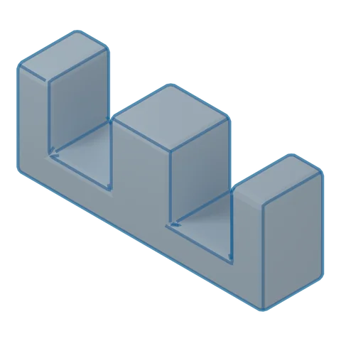 3D · illustrativeEE/EPChoose a series ▾
Strengths
- Easiest bobbin winding and assembly
- Best heat dissipation
- Low core cost
Trade-offs
- Weak self-shielding, higher leakage flux
- Needs a bobbin; for low height use EFD
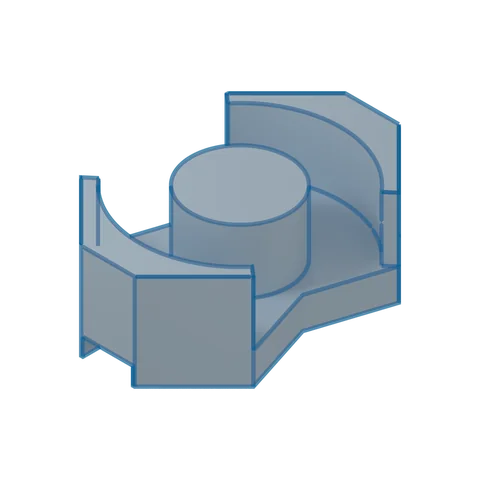 3D · illustrativeRMChoose a series ▾
Strengths
- Saves PCB area; low height possible
- Encloses the winding: good shielding, good heat dissipation
- Center leg can be ground for an air gap to set AL
Trade-offs
- Higher core cost
- Lead-out of thick wire is limited
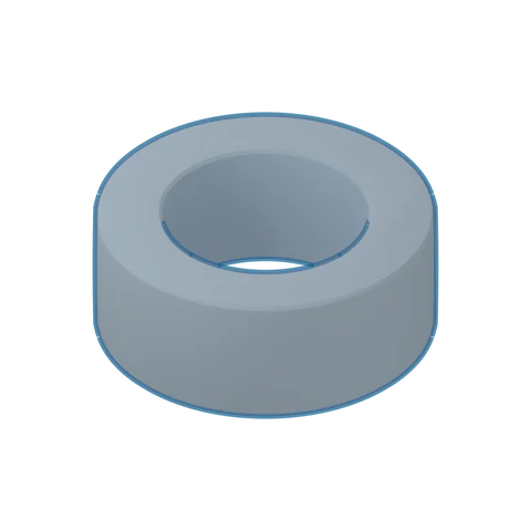 3D · illustrativeToroid TChoose a series ▾
Strengths
- Closed magnetic path without joints or air gap: highest magnetic efficiency
- Good self-shielding, low leakage flux
- Lowest core cost, no bobbin needed
Trade-offs
- Winding must be threaded through the hole; high winding cost
- Less convenient to mount on the PCB
- No air gap; for storage inductors use a combination shape whose gap can be ground
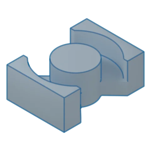 3D · illustrativePQChoose a series ▾
Strengths
- Optimized for switch-mode power: good ratio of volume, winding window and magnetic cross-section
- Center leg can be ground for an air gap to set AL
- Simple winding and assembly, good heat dissipation
Trade-offs
- Higher core and bobbin cost
- Moderate shielding; less convenient to mount on the PCB
Where it goes
UPS, battery-backup conversion
Isolated gate-drive supplies for traction inverters
12/24 V low-voltage input converters, inverters