 TAK Technology
G5B
HIGH PERM. & HIGH FLUX & EMI MATERIALS
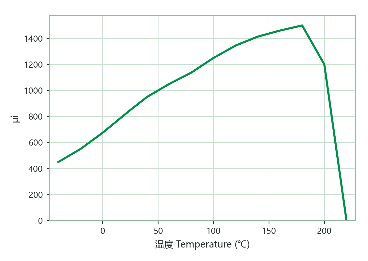
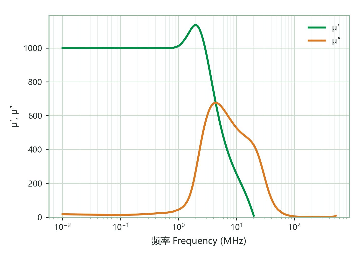
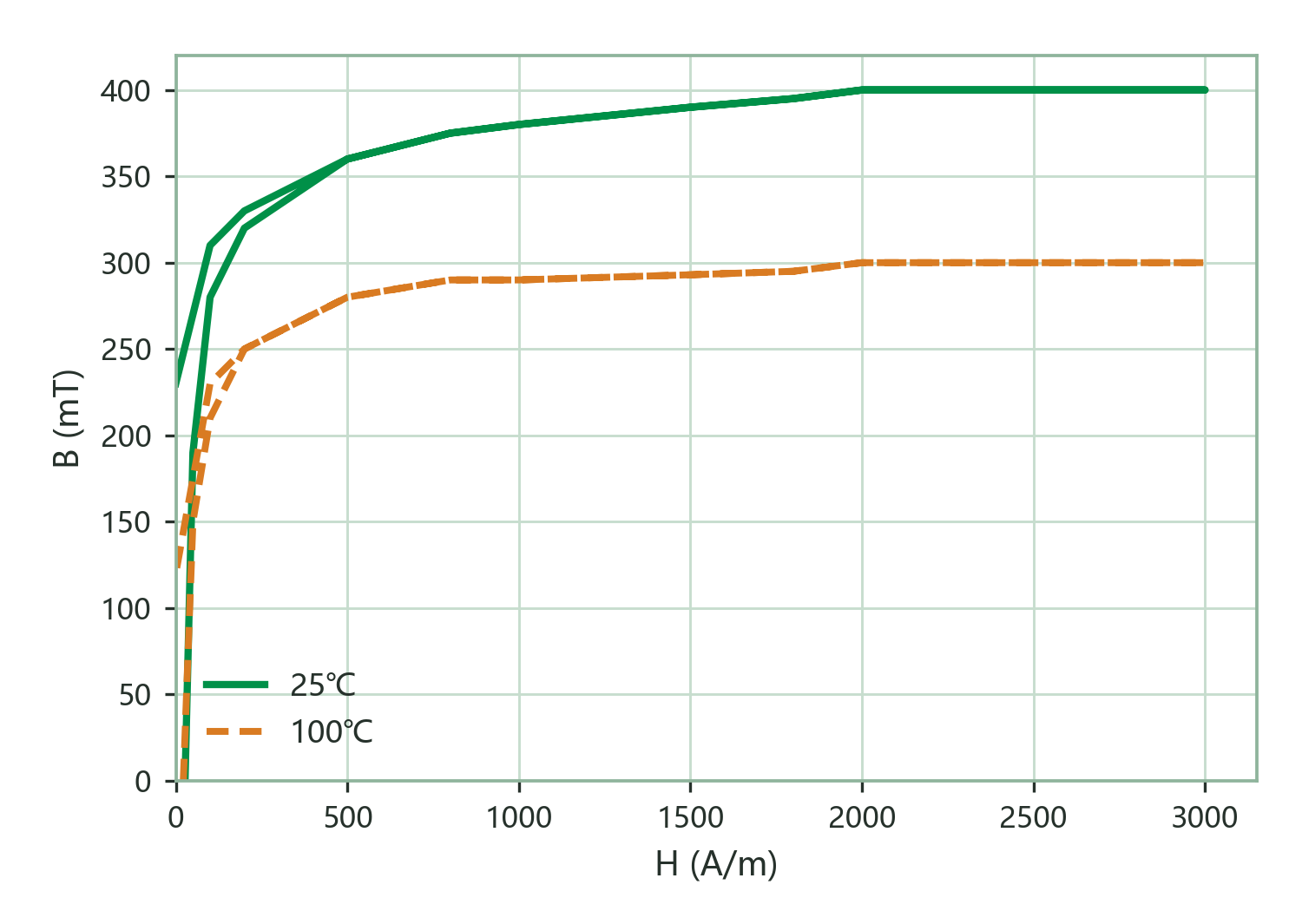
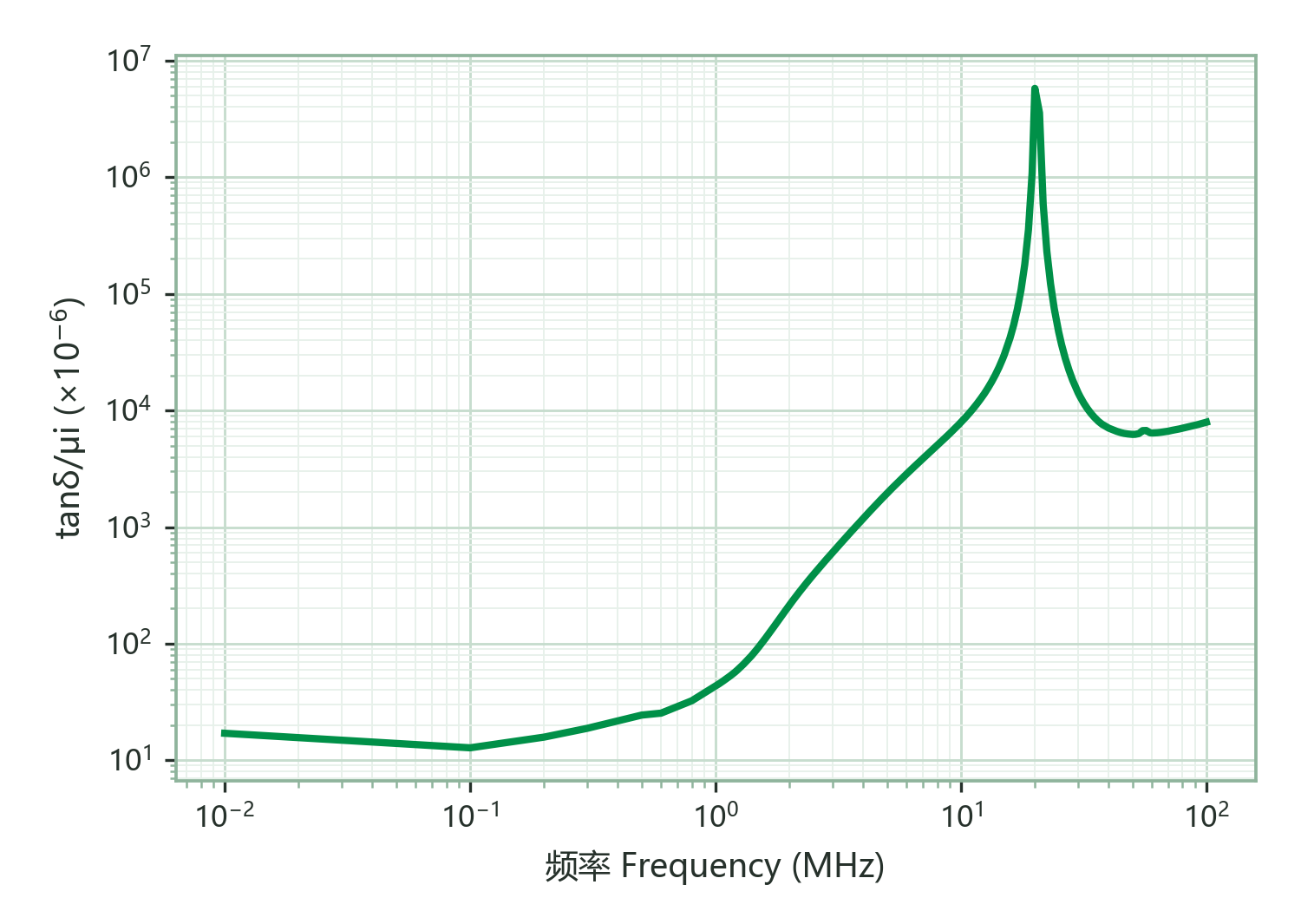
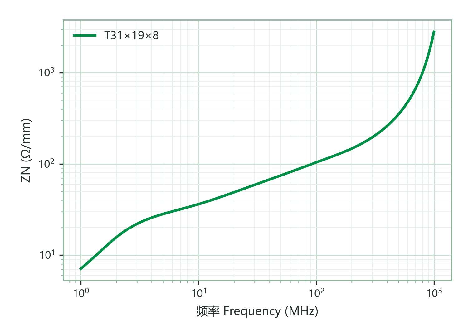
G5B is a NiZn ferrite with an initial permeability (μi) of approx. 1000, a saturation flux density (Bs) of approx. 390 mT at 25 °C (300 mT at 100 °C) and a Curie temperature above 180 °C. It raises the G5 family's nominal permeability by a further 25 % while keeping the high saturation flux: common-mode filters reach the same impedance with fewer turns, and power inductors gain energy-storage and inductance density; with a coercivity of only 25 A/m the hysteresis loss stays low, and the loss factor is 15×10⁻⁶ at 0.1 MHz / 45×10⁻⁶ at 1.0 MHz. Typical uses are power modules, current-compensated inductors and common-/differential-mode filters, including ADAS and motor-drive EMC protection in automotive. Against G5A (μi approx. 800, Bs approx. 400 mT, Tc >190 °C): Bs and temperature rating are on the same level; G5B leads in impedance and inductance density while G5A is slightly lower-loss at the 1 MHz end (30 vs 45×10⁻⁶) — pick G5A when the upper band dominates the design, G5B for most other common-mode and power duties.
Magnetic Characteristics
| Characteristic | Condition | Value | Unit |
|---|---|---|---|
| μiInitial Permeability | 100 kHz & <0.2 mT | 1000±25% | — |
| BsSaturation Flux Density | 3000 A/m · 25 ℃100 Hz | 390 | mT |
| BsSaturation Flux Density | 3000 A/m · 100 ℃100 Hz | 300 | mT |
| BrRemanence | 3000 A/m · 25 ℃100 Hz | 235 | mT |
| BrRemanence | 3000 A/m · 100 ℃100 Hz | 150 | mT |
| HcCoercivity | 3000 A/m · 25 ℃100 Hz | 25 | A/m |
| HcCoercivity | 3000 A/m · 100 ℃100 Hz | 20 | A/m |
| αμrTemperature coefficient of permeability | 20~60 ℃ | 8 | ×10⁻⁶/K |
| tanδ/μiRelative Loss Factor | 0.1 MHz & <0.2 mT | 15 | ×10⁻⁶ |
| tanδ/μiRelative Loss Factor | 1.0 MHz & <0.2 mT | 45 | ×10⁻⁶ |
| TcCurie Temp. | 100 kHz & <0.2 mT | >180 | ℃ |
| DDensity | Archimedes method | 5.1 | g/cm³ |
| ρVolume Resistivity | DC Current | 10⁷ | Ω·m |
| PcvPower Loss | 100 kHz/100 mT|500 kHz/30 mT|1 MHz/30 mT · 25 °C | 460|264|832 | kW/m³ |
Characteristic curves
Applications
| Application | Role | Band | Temperature |
|---|---|---|---|
| SMD HF low-power inductor (mA level) | First choice | ≤2.5 MHz | — |
| Common-mode choke / mains EMI filter | Alternative | 2–30 MHz | — |
| EMI bead / ring / cable sleeve | Alternative | 2–100 MHz | — |