 TAK Technology
EP + I CoreE-type Cores
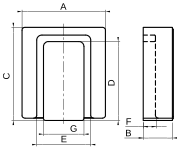
Fig.1
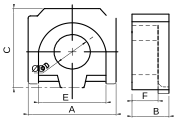
| P/N | Dimensions · mm (nominal / tolerance) | Effective parameters F | |||||||||||
|---|---|---|---|---|---|---|---|---|---|---|---|---|---|
| A(mm) | B(mm) | C(mm) | D(mm) | E(mm) | F(mm) | G(mm) | C1mm⁻¹ | C2mm⁻³ | Lemm | Aemm² | Vemm³ | ≈Wtg | |
| EP5.6×5.3×2.35 + I5.6×5.85×1.4 | 5.60±0.105.60±0.10 | 2.35±0.101.40±0.10 | 5.30±0.105.85±0.10 | 2.30±0.10 | 4.30±0.10 | 1.65±0.10 | — | — | — | — | — | — | — |
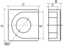
Fig.2
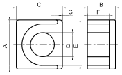
| P/N | Dimensions · mm (nominal / tolerance) | Effective parameters F | |||||||||||
|---|---|---|---|---|---|---|---|---|---|---|---|---|---|
| A(mm) | B(mm) | C(mm) | D(mm) | E(mm) | F(mm) | G(mm) | C1mm⁻¹ | C2mm⁻³ | Lemm | Aemm² | Vemm³ | ≈Wtg | |
| EP10.2×9.7×5.8 + I10.2×9.7×1.3 | 10.20±0.2010.20±0.20 | 5.80±0.101.30±0.10 | 9.70±0.159.70±0.20 | 5.00±0.102.80±0.15 | 8.60±0.202.20±0.15 | 4.50±0.10/ | 1.00±0.151.15±0.05 | 0.5650 | 0.0283 | 11.30 | 20.00 | 226.00 | 2.14 |
| EP12.6×12.5×4.15 + I12.6×11.7×1.45 | 12.60±0.1512.60±0.15 | 4.15±0.101.45±0.10 | 12.50+0.20/-0.1011.70+0.20/-0.10 | 5.80+0.05/-0.102.35+0.20/-0.10 | 11.00±0.203.20±0.10 | 2.55±0.10/ | 1.55ref0.80±0.10 | / | / | / | / | / | 1.95 |
| EP23.1×23×10.4 + I22.9×22.35×2.97 | 23.10±0.3023.10±0.30 | 10.40±0.103.05±0.15 | 23.00±0.3522.50±0.35 | 11.50±0.2011.60±0.25 | 20.45±0.3021.00±0.35 | 7.40±0.152.20max | 1.00ref4.30±0.20 | / | / | / | / | / | 15.06 |
Fig.3
| P/N | Dimensions · mm (nominal / tolerance) | Effective parameters F | |||||||||||
|---|---|---|---|---|---|---|---|---|---|---|---|---|---|
| A(mm) | B(mm) | C(mm) | D(mm) | E(mm) | F(mm) | G(mm) | C1mm⁻¹ | C2mm⁻³ | Lemm | Aemm² | Vemm³ | ≈Wtg | |
| EP10.3×9.57×2.57 + I10.3×9.57×1.06 | 10.30±0.1510.30±0.15 | 2.57±0.101.06±0.10 | 9.57±0.159.57±0.15 | 7.18±0.10 | 7.85±0.12 | 1.09±0.10 | 4.26±0.10 | / | / | / | / | / | 0.9900 |
| EP10.7×9.5×2.55 + I10.7×9.55×1.6 | 10.70±0.1510.70±0.15 | 2.55±0.101.60±0.10 | 9.50±0.159.50±0.15 | 7.20±0.10 | 7.80±0.15 | 0.93±0.08 | 4.40±0.10 | / | / | / | / | / | 1.02 |
Fig.4
| P/N | Dimensions · mm (nominal / tolerance) | Effective parameters F | |||||||||||
|---|---|---|---|---|---|---|---|---|---|---|---|---|---|
| A(mm) | B(mm) | C(mm) | D(mm) | E(mm) | F(mm) | G(mm) | C1mm⁻¹ | C2mm⁻³ | Lemm | Aemm² | Vemm³ | ≈Wtg | |
| EP17×16×7.3 + I17×16×2.5 | 17.00±0.2517.00±0.25 | 7.30±0.152.50±0.10 | 16.00±0.2516.00±0.25 | 8.60±0.188.20±0.20 | 14.40±0.203.00±0.10 | 5.45±0.101.35±0.10 | /14.40±0.20 | — | — | — | — | — | — |
| EP19.1×18.8×7.6 + I19.1×18.8×2.2C | 19.10±0.3019.50max | 7.60±0.102.30±0.15 | 18.80±0.3019.00±0.30 | 9.20±0.159.35±0.25 | 16.20±0.302.60±0.15 | 5.30±0.151.30±0.10 | /16.15±0.20 | / | / | / | / | / | 7.69 |
This table only shows common product numbers. If the EP core you need is not listed in the above table, please do not hesitate to contact us.
Calculated from nominal dimensions per IEC 60205: C1 = ΣL/A, C2 = ΣL/A², Le = C1²/C2, Ae = C1/C2, Ve = Le×Ae; Amin = minimum cross-section; values for paired sets apply to the assembled set. ≈Wt is a reference fired-core weight — actual values vary with material and sintering, not a specification commitment; part numbers not listed have no effective-parameter data yet. Values are for the assembled set of one EP half plus one I plate: an asymmetric loop (I plate on one side, window height of a single half F) evaluated with the IEC 60205 segment method. They differ from EP pair values (two halves, window 2F) and are not interchangeable; only the plate thickness enters the magnetic path.