 TAK Technology
M61H
HIGH FREQUENCY STABLE MATERIALS
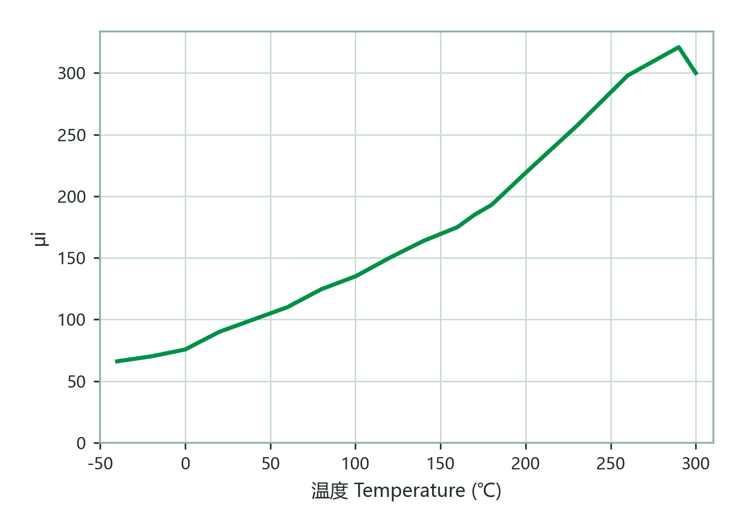
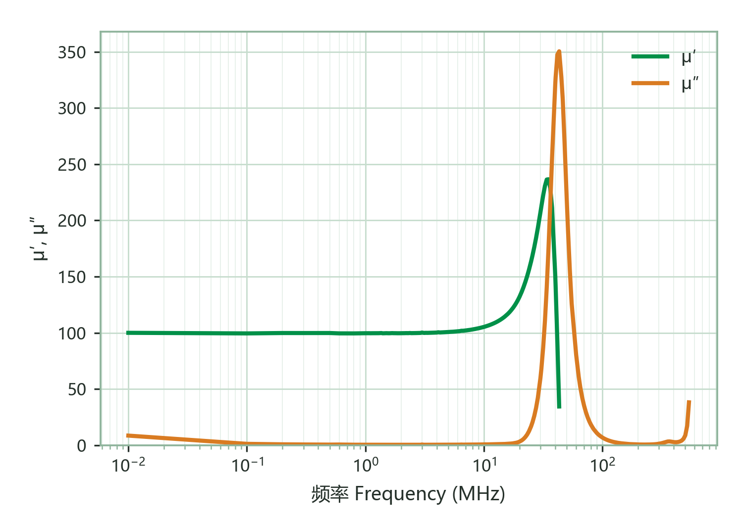
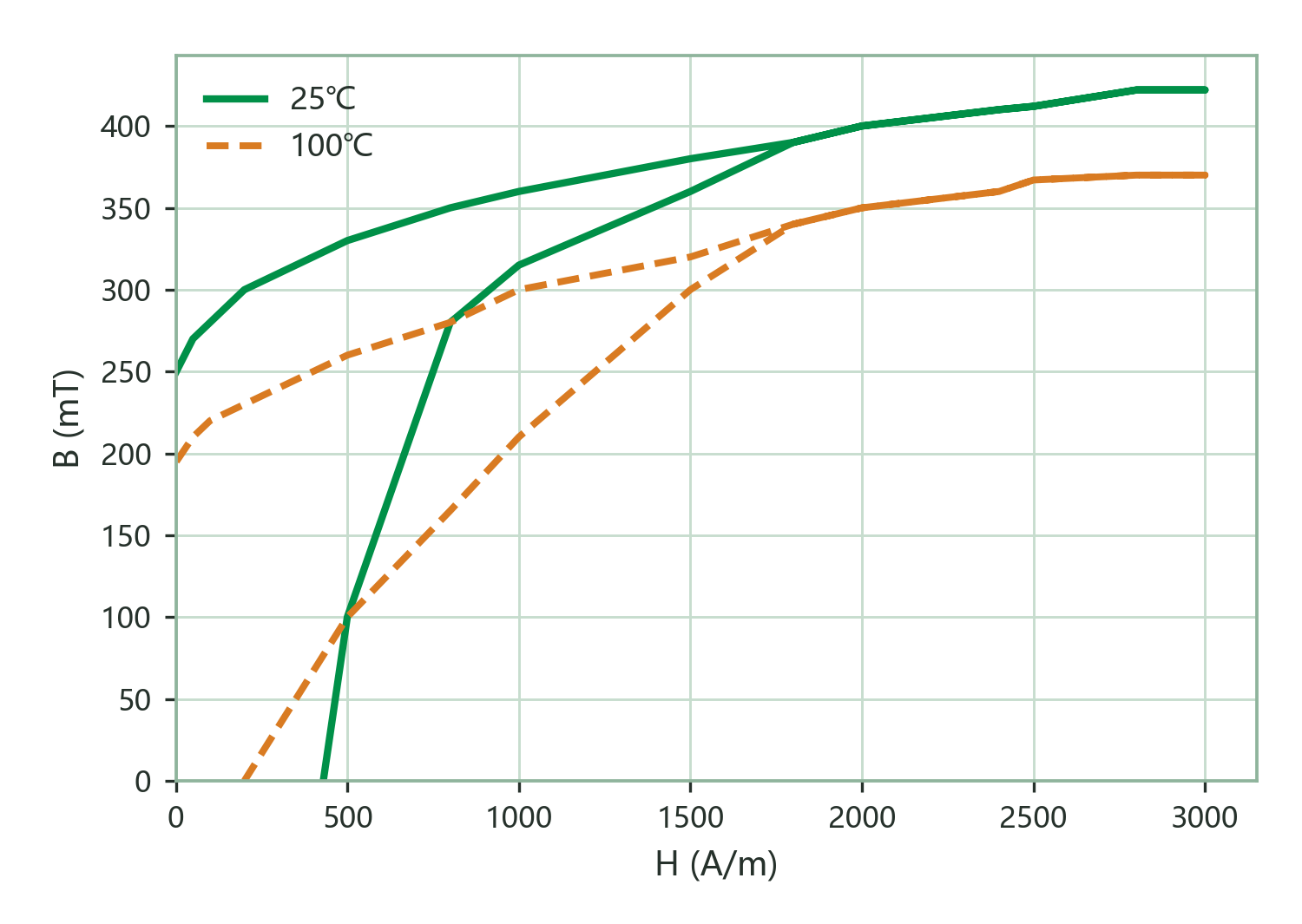
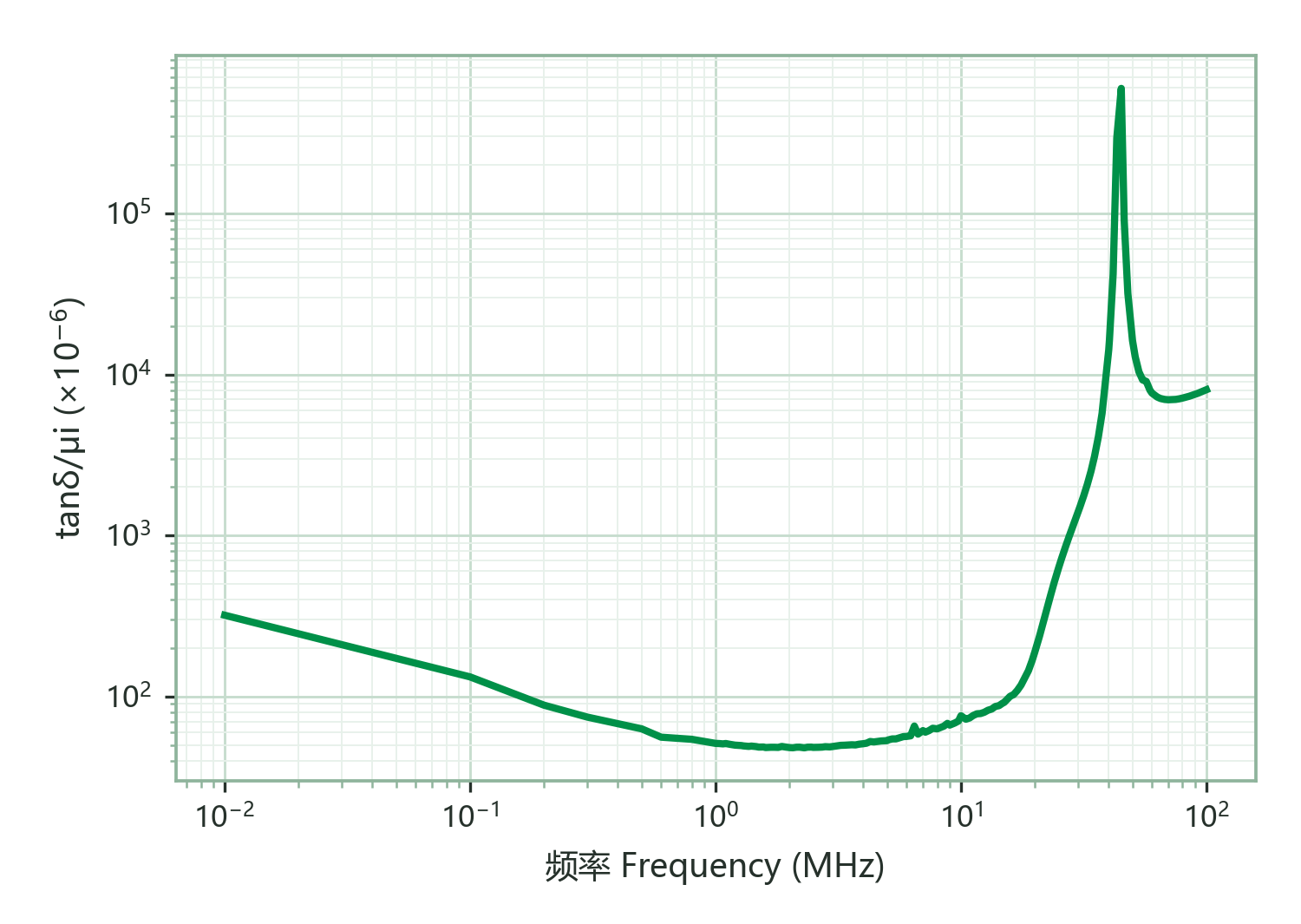
M61H is a NiZn ferrite with an initial permeability (μi) of approx. 100, a saturation flux density (Bs) of approx. 420 mT at 25 °C (370 mT at 100 °C) and a Curie temperature above 280 °C. It shares M61's permeability step but pushes the saturation flux to 420 mT with 370 mT retained at 100 °C — greatly enlarging the flux margin of HF inductors under heavy DC bias; the loss factor stays low at 50×10⁻⁶ (1.0 and 5.0 MHz), so loss behaviour under power is equally strong. Typical uses are high-current HF inductors, wireless-charging coils and high-temperature RF power filters. Division of labour with M61: M61's near-zero temperature coefficient (approx. −2×10⁻⁶/K) suits drift-sensitive filtering and tuning; M61H accepts a slightly higher coefficient (approx. 15×10⁻⁶/K) and a slightly lower Curie point (>280 °C vs >300 °C) in exchange for the family's highest flux capability — choose M61H wherever power flows.
Magnetic Characteristics
| Characteristic | Condition | Value | Unit |
|---|---|---|---|
| μiInitial Permeability | 100 kHz & <0.2 mT | 100±25% | — |
| BsSaturation Flux Density | 3000 A/m · 25 ℃100 Hz | 420 | mT |
| BsSaturation Flux Density | 3000 A/m · 100 ℃100 Hz | 370 | mT |
| BrRemanence | 3000 A/m · 25 ℃100 Hz | 255 | mT |
| BrRemanence | 3000 A/m · 100 ℃100 Hz | 195 | mT |
| HcCoercivity | 3000 A/m · 25 ℃100 Hz | 105 | A/m |
| HcCoercivity | 3000 A/m · 100 ℃100 Hz | 95 | A/m |
| αμrTemperature coefficient of permeability | 20~60 ℃ | 15 | ×10⁻⁶/K |
| tanδ/μiRelative Loss Factor | 1.0 MHz & <0.2 mT | 50 | ×10⁻⁶ |
| tanδ/μiRelative Loss Factor | 5.0 MHz & <0.2 mT | 50 | ×10⁻⁶ |
| TcCurie Temp. | 100 kHz & <0.2 mT | >280 | ℃ |
| DDensity | Archimedes method | 5.0 | g/cm³ |
| ρVolume Resistivity | DC Current | 10⁷ | Ω·m |
Characteristic curves
Applications
| Application | Role | Band | Temperature |
|---|---|---|---|
| Small-power HF transformer (low flux) | Alternative | 5–15 MHz | — |
| Wideband signal transformer / balun | Alternative | ≤15 MHz | — |
| Antenna rod / RFID / high-Q inductor | First choice | 0.5–9.8 MHz | — |
| Low-μ tuning / HF resonance | First choice | 0.5–9.8 MHz | — |